Hardware Design
In the second part of the hardware section we will look at how the receiver was built step by step. Follow along with the schematic and you'll get a good feeling for how things come together and the stages I use when building electronics on a breadboard.
Building The Circuit
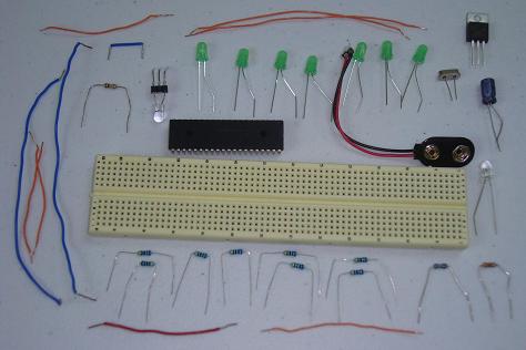
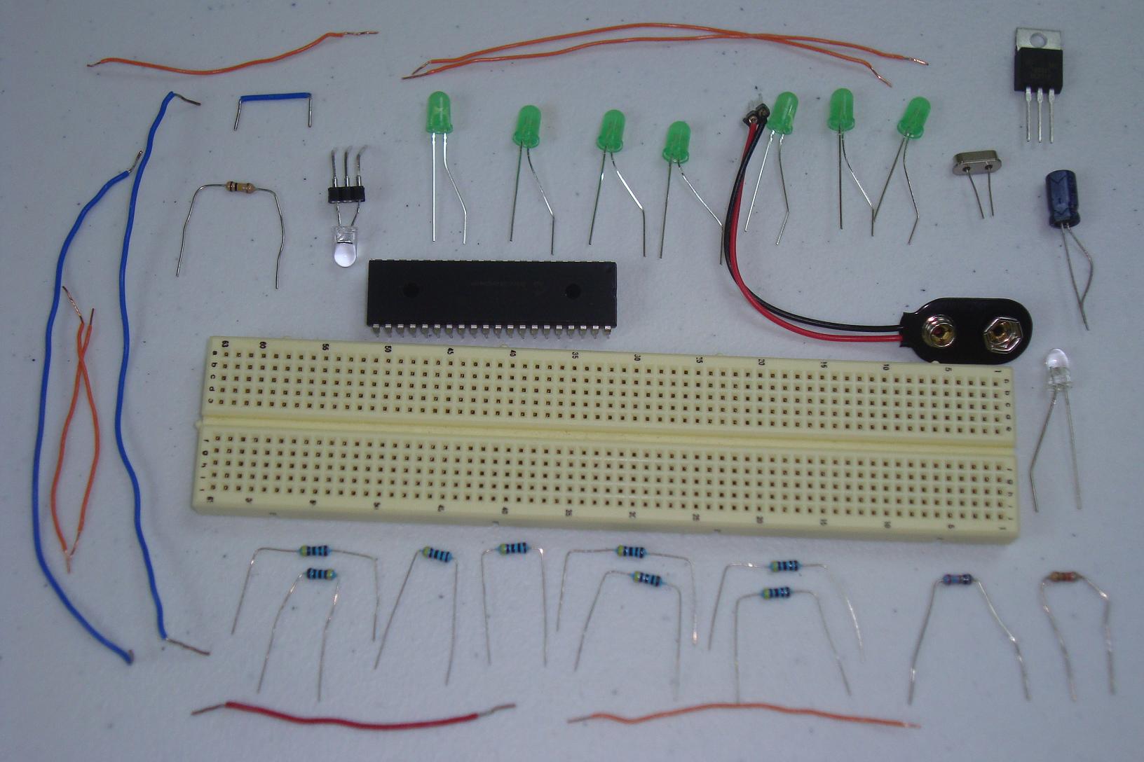
Just like before, I laid out all the parts on my workbench, ready to be assembled into the breadboard. The receiver does have significantly more parts, so it will take a little longer to get this one right.
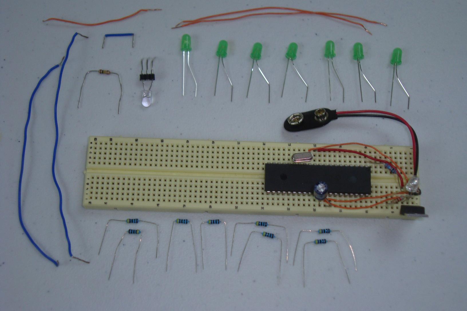
·Start by assembling the power regulation (7805) circuit on the breadboard.
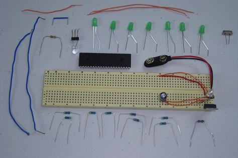
·The PIC circuit is added next with 4 MHz crystal and 10kΩ resistor.

·Resistors are added to each pin of PORTD on the PIC for output.
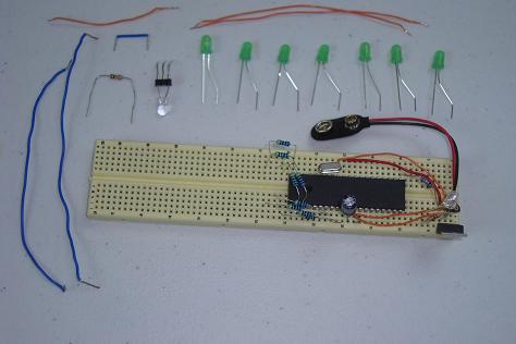
·LEDs are connected to the resistors and then to ground.
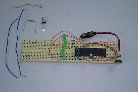
·The final step is connecting the RX pin on the PIC to the phototransistor.
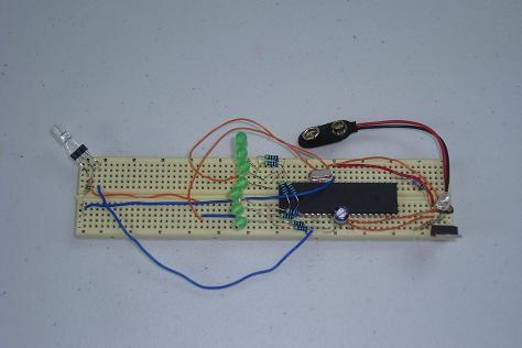
·After some effort, the circuit has been built on the breadboard and is ready for some software.
In the second part of the hardware section we will look at how the receiver was built step by step. Follow along with the schematic and you'll get a good feeling for how things come together and the stages I use when building electronics on a breadboard.
Building The Circuit
Just like before, I laid out all the parts on my workbench, ready to be assembled into the breadboard. The receiver does have significantly more parts, so it will take a little longer to get this one right.
·Start by assembling the power regulation (7805) circuit on the breadboard.

·The PIC circuit is added next with 4 MHz crystal and 10kΩ resistor.
·Resistors are added to each pin of PORTD on the PIC for output.
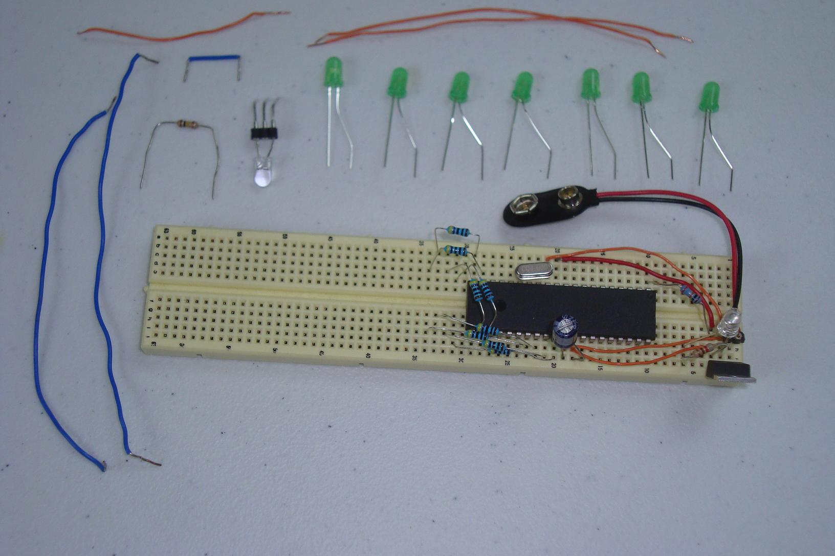
·LEDs are connected to the resistors and then to ground.
·The final step is connecting the RX pin on the PIC to the phototransistor.
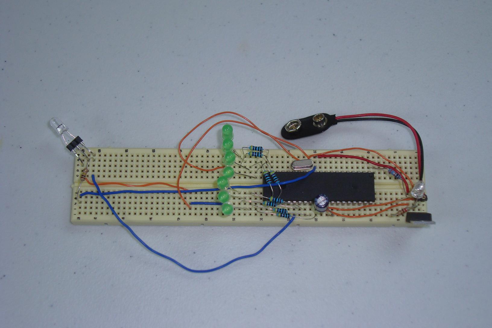
·After some effort, the circuit has been built on the breadboard and is ready for some software.