Schematic Overview
Two circuits need to be built for this tutorial; the transmitter and the receiver. These two circuits are not over-complex in anyway so hopefully acquiring the parts and assembling everything should be straight forward. The main parts to take note of in these two circuits are the 7805, 18F452, 2N2222, Phototransistor and IR Emitter LED.
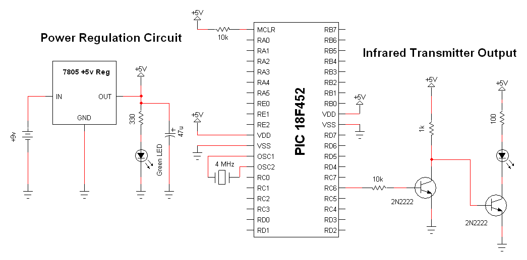
Wireless Infrared Link Transmitter Schematic
View Full Schematic
Schematic Specifics
Power Circuit
The power circuit (regulator) is the same in both transmitter and receiver because all we need a +5v regulated power supply to operate the digital electronics. The 7805 linear regulator was chosen because it is cheap and widely available.
Microcontroller Circuit
The transmitting microcontroller will be a PIC 18F452. The USART module inside of this microcontroller will be used to send the asynchronous serial data. The microcontroller will continuously send a count value from 0 to 8 and then repeat.
Infrared Transmitter Circuit
The PIC's digital USART RC6 Tx output port cannot supply enough current to give the IR emitter LED the power it really needs, so a buffer circuit is used with 2x 2N2222 transistors so that the IR Emitter LED is driven from the main +5v regulated power supply.
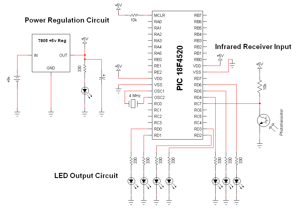
Wireless Infrared Link Receiver Schematic
View Full Schematic
Schematic Specifics
Power Circuit
The power circuit (regulator) is the same in both transmitter and receiver because all we need a +5v regulated power supply to operate the digital electronics. The 7805 linear regulator was chosen because it is cheap and widely available.
Microcontroller Circuit
To make things as simple as possible, the receiving microcontroller will be the same as the transmitter: PIC 18F452. The other half of the USART module will be used to receive the data, rather than transmit and then the PIC will decide how many LEDs to light up, 0 to 8, depending upon the transmitted ASCII value, 0 to 8.
Infrared Receiving Circuit
This circuit consists of a photo transistor and 1x 10kΩ resistor with some connections to ground and power. The collector pin of the phototransistor is connected to the PIC's RC7 input also known as the USART Rx input.
Two circuits need to be built for this tutorial; the transmitter and the receiver. These two circuits are not over-complex in anyway so hopefully acquiring the parts and assembling everything should be straight forward. The main parts to take note of in these two circuits are the 7805, 18F452, 2N2222, Phototransistor and IR Emitter LED.
View Full Schematic
Schematic Specifics
Power Circuit
The power circuit (regulator) is the same in both transmitter and receiver because all we need a +5v regulated power supply to operate the digital electronics. The 7805 linear regulator was chosen because it is cheap and widely available.
Microcontroller Circuit
The transmitting microcontroller will be a PIC 18F452. The USART module inside of this microcontroller will be used to send the asynchronous serial data. The microcontroller will continuously send a count value from 0 to 8 and then repeat.
Infrared Transmitter Circuit
The PIC's digital USART RC6 Tx output port cannot supply enough current to give the IR emitter LED the power it really needs, so a buffer circuit is used with 2x 2N2222 transistors so that the IR Emitter LED is driven from the main +5v regulated power supply.
View Full Schematic
Schematic Specifics
Power Circuit
The power circuit (regulator) is the same in both transmitter and receiver because all we need a +5v regulated power supply to operate the digital electronics. The 7805 linear regulator was chosen because it is cheap and widely available.
Microcontroller Circuit
To make things as simple as possible, the receiving microcontroller will be the same as the transmitter: PIC 18F452. The other half of the USART module will be used to receive the data, rather than transmit and then the PIC will decide how many LEDs to light up, 0 to 8, depending upon the transmitted ASCII value, 0 to 8.
Infrared Receiving Circuit
This circuit consists of a photo transistor and 1x 10kΩ resistor with some connections to ground and power. The collector pin of the phototransistor is connected to the PIC's RC7 input also known as the USART Rx input.