Schematic Overview
The UP1 board itsself is very complex and so no simple schematic exists. The schematic below gives you a high level overview of what is on the board and where it is at. Take a close look at the CPLD (EPM7128S), the LEDs, Switches and 7 segment digits. These are what we'll be using in this tutorial
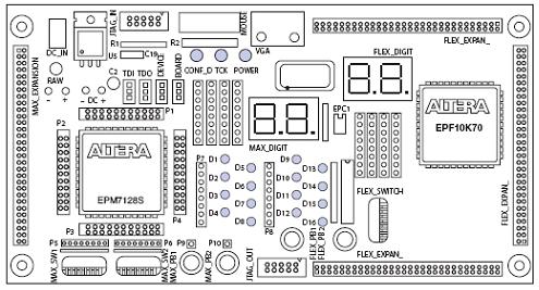
Aside from the simple overview schematic, we'll need to know the hardwired pins to the 7 segment digit displays. The picture and tables below show you which pins off the CPLD are hooked up to exactly which segment on each particular led.
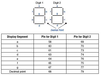
With this knowledge in mind, let's take a step forward and look at the theory behind the simple logic adder. It only uses a few logic gates!
The UP1 board itsself is very complex and so no simple schematic exists. The schematic below gives you a high level overview of what is on the board and where it is at. Take a close look at the CPLD (EPM7128S), the LEDs, Switches and 7 segment digits. These are what we'll be using in this tutorial
Aside from the simple overview schematic, we'll need to know the hardwired pins to the 7 segment digit displays. The picture and tables below show you which pins off the CPLD are hooked up to exactly which segment on each particular led.
With this knowledge in mind, let's take a step forward and look at the theory behind the simple logic adder. It only uses a few logic gates!