Hardware Design
Moving beyond the schematic let's take a look at the actual parts on the board. The picture below has most everything labeled out.
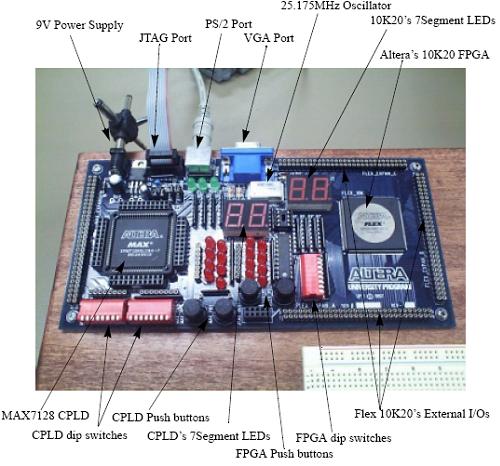
This is broaden your understanding of exactly what is on the board where and make it easier when you're searching through the users manual trying to figure out what a ceratin part does or how to do some certain thing.
On the same topic; the manual for this board is oddly enough quite thourough. You can get the PDF off of altera's website or if you bought the board it comes with it. The pinouts for the VGA/PS2/7 Segments & everything are listed nicely in tables through the manual.
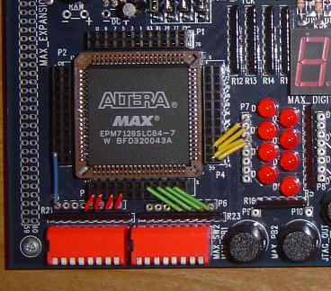
In addition to taking a look at the board we will eventually need to wire it up. On each side of the EPM7128S CPLD socket there are spots for wires to plug in. Similarly by the LEDs and DIP switches there are spots for wires. Giving you the reader & explorer a little le-way, you can choose which wires will hook up to which pin on the CPLD. As an example the picture above shows how I did it.
Moving beyond the schematic let's take a look at the actual parts on the board. The picture below has most everything labeled out.
This is broaden your understanding of exactly what is on the board where and make it easier when you're searching through the users manual trying to figure out what a ceratin part does or how to do some certain thing.
On the same topic; the manual for this board is oddly enough quite thourough. You can get the PDF off of altera's website or if you bought the board it comes with it. The pinouts for the VGA/PS2/7 Segments & everything are listed nicely in tables through the manual.
In addition to taking a look at the board we will eventually need to wire it up. On each side of the EPM7128S CPLD socket there are spots for wires to plug in. Similarly by the LEDs and DIP switches there are spots for wires. Giving you the reader & explorer a little le-way, you can choose which wires will hook up to which pin on the CPLD. As an example the picture above shows how I did it.