The Guts of The DMM
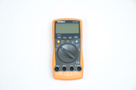
For those of you who love a quick and simple tear down of electronics, this section is for you. Now we'll take a look at the disassembly process of the DMM to see what is 'under-the-hood' making all the magic happen.
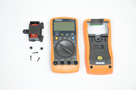
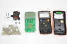
The photos above show that disassembly of this DMM is actually fairly straight forward with only 8 screws holding the case and PCB together. A second PCB can be seen attached to the top of the DMM. This holds the IR circuit for connecting to a PC with RS232.
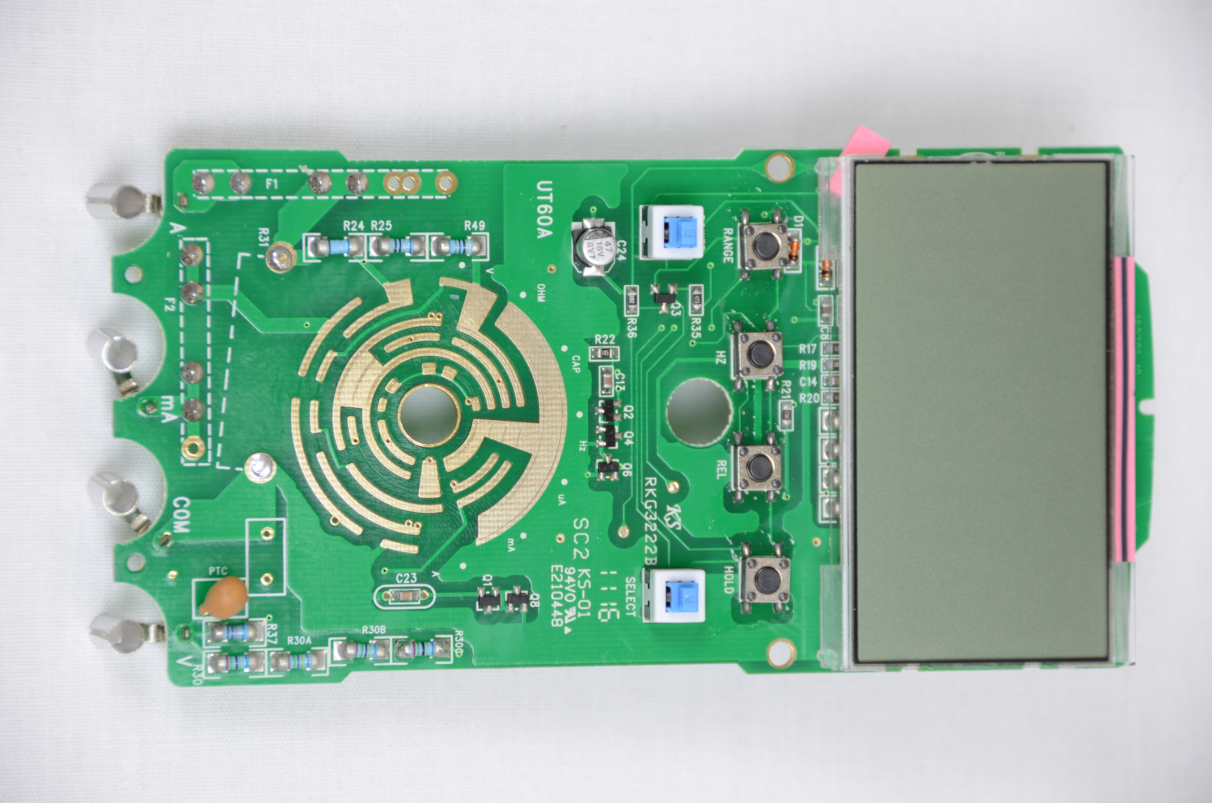
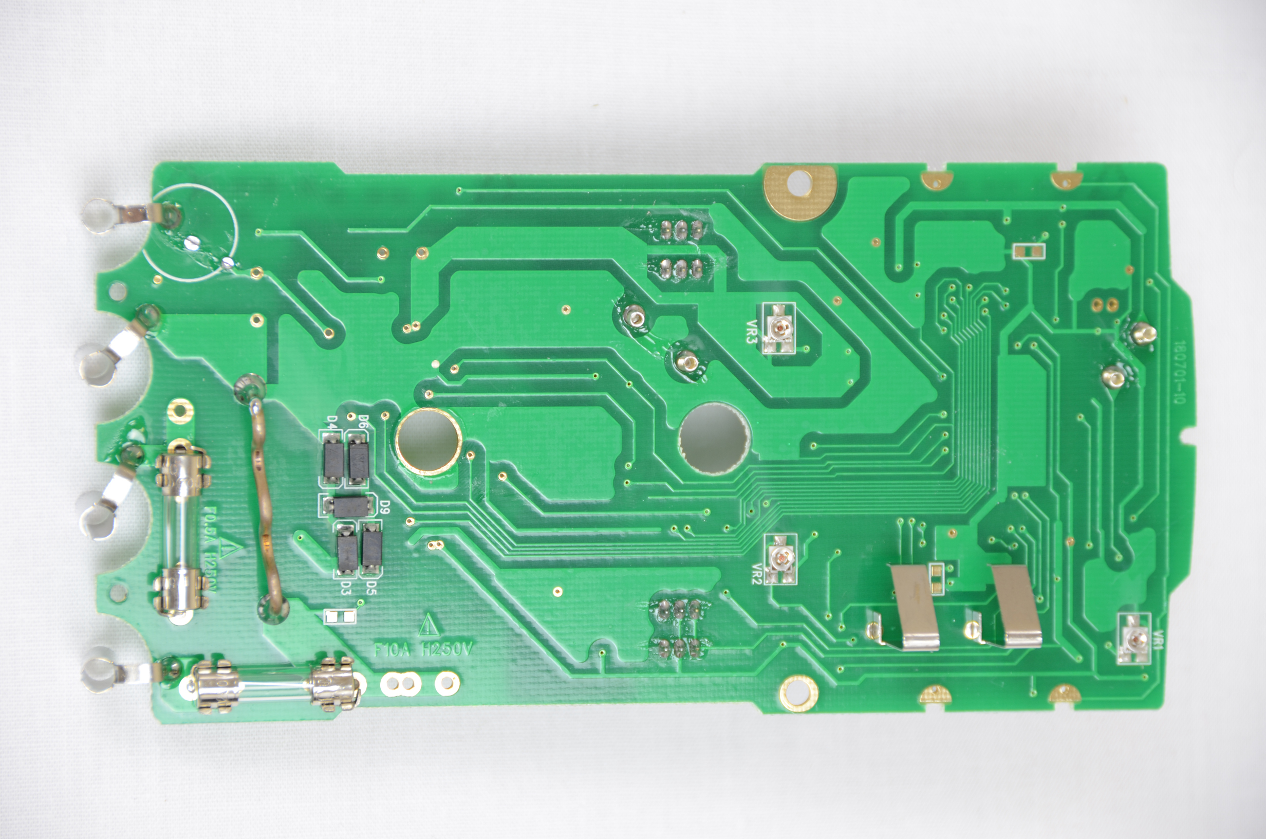
Upon closer inspection of the Tenma 72-7735's PCB itself, it looked to be a decent quality 2 layer board. The sheer number of components used in the design is a dead give-away that someone at least tried to do a good job compared to some cheap DMM's that come out of china that have only 1 IC and 5 other components on the PCB.
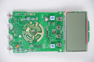

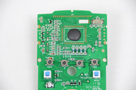
After I removed the LCD from the PCB it was obvious where all the brains of this circuit were, hidden under a blob of black epoxy. From the looks of it this DMM uses some microcontroller with a 4 MHz crystal doing a ton of A/D conversions to output the vales to the display. Again, the number of components and layout work looks like the designer actually wanted to make a good product, which is always a promising sign.
Since everything was already taken apart, I took the liberty of cleaning of those extra pieces of plastic that were annoying me back in the features section. They turned out to just be small pieces of plastic dust that came right off. The display (seen above) is now clean and free of any specs of dust or plastic!
For those of you who love a quick and simple tear down of electronics, this section is for you. Now we'll take a look at the disassembly process of the DMM to see what is 'under-the-hood' making all the magic happen.
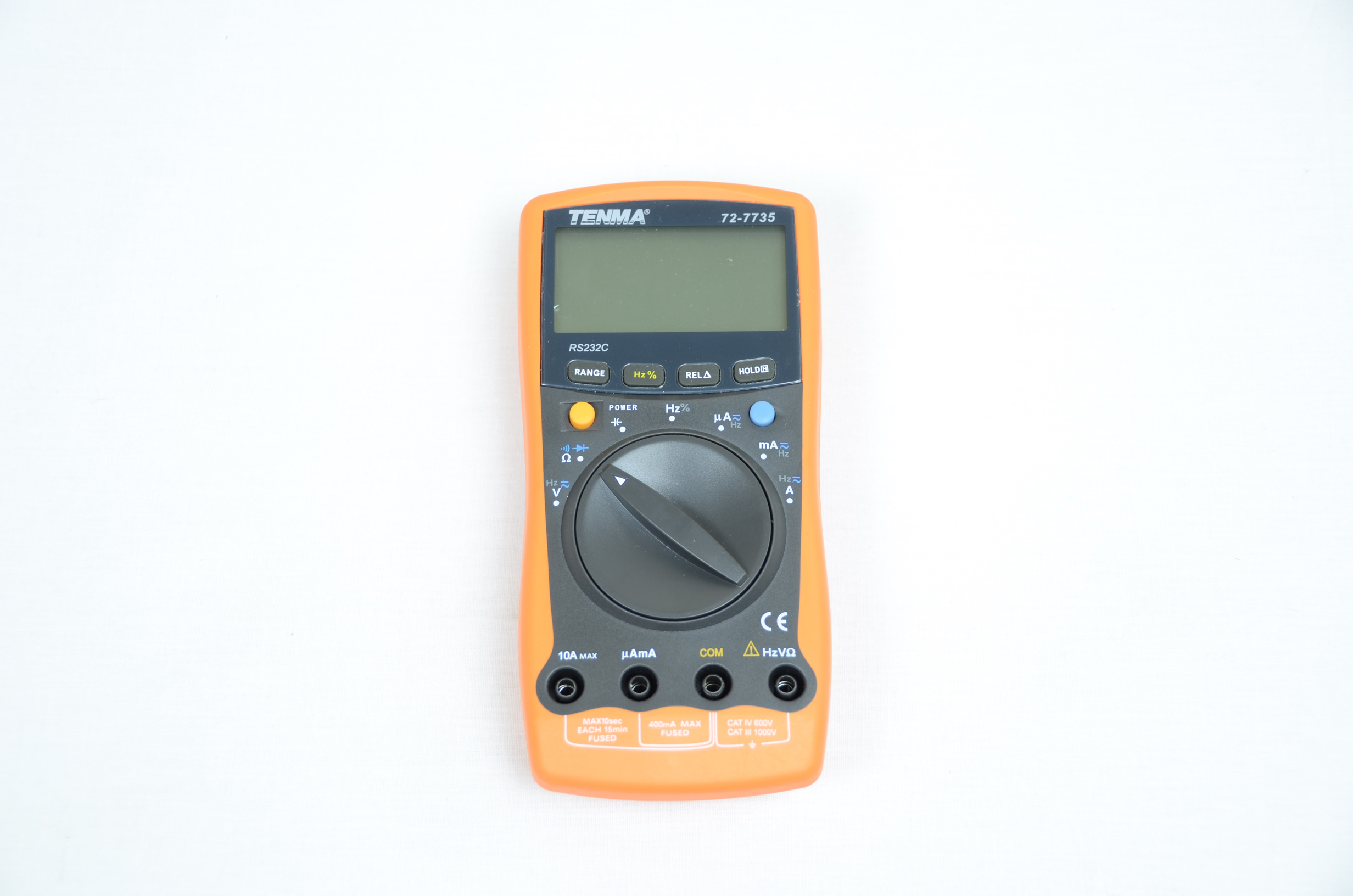


The photos above show that disassembly of this DMM is actually fairly straight forward with only 8 screws holding the case and PCB together. A second PCB can be seen attached to the top of the DMM. This holds the IR circuit for connecting to a PC with RS232.
Upon closer inspection of the Tenma 72-7735's PCB itself, it looked to be a decent quality 2 layer board. The sheer number of components used in the design is a dead give-away that someone at least tried to do a good job compared to some cheap DMM's that come out of china that have only 1 IC and 5 other components on the PCB.

After I removed the LCD from the PCB it was obvious where all the brains of this circuit were, hidden under a blob of black epoxy. From the looks of it this DMM uses some microcontroller with a 4 MHz crystal doing a ton of A/D conversions to output the vales to the display. Again, the number of components and layout work looks like the designer actually wanted to make a good product, which is always a promising sign.

Since everything was already taken apart, I took the liberty of cleaning of those extra pieces of plastic that were annoying me back in the features section. They turned out to just be small pieces of plastic dust that came right off. The display (seen above) is now clean and free of any specs of dust or plastic!