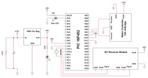
Schematic Overview
The Quick and Easy Wireless circuit is not terribly difficult however it will take some double checking to make sure you have everything hooked up properly before working the first time. The main devices used in the circuit are the 7805, 18F452, RC Receiver and RC Transmitter.
View Full Schematic
Schematic Specifics
Power Circuit
The 7805 regulates the +9v battery down to +5v which the PIC and all other devices want to see. The DC filtering capacitor used is 47uF and after this cap all devices are ready to see the power supply.
Microcontroller Circuit
The microcontroller circuit is where the input and output control is happening. The transmitter has two output signals going to the microcontroller, which get interpreted and then passed on to control the output devices (LED/Motor).
RC Receiver Module
The transmitter is its own stand-alone device that transmits certain types of signals that the receiver understands and outputs, so it doesn't appare on the schematic.
The Receiver module, however, does connect to the PIC on PORTC so we can see that the receiver uses the same power supply as the pic and two signal lines are connecting to it as well.
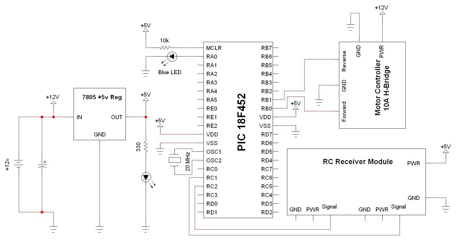