Hardware Design
We saw the schematic and a little theory, so now let's build it! Another quick look over the parts list shows you everything you need, which forunately is only a few parts and a lot of wires.
Building The Circuit
Get your parts together and follow the schematic. I build mine and in stages as you can see below...

·A standard white breadboard. It's one of my favorites as they're cheap but realiable.

·First I build the power circuit. An LM7805 is used, its a standard +5v regulator. Some wires are added as well to connect the power, and ground buses together. A DC filtering cap is also added.

·Now I put the microcontroller circuit on the breadboard and wired it up to the power supply circuit.

·The next step is adding the LED output and two wires from Pins 16 and 17, which are the PIC's CCP2 and CCP1.
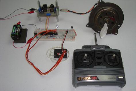
·The last step is connecting the receiver outputs, receiver power and H-bridge motor controller to the breadboard.