Explanation of the Code
The p18f452.h include file gives us easy access to the different ports & registers that this PIC uses. Each different version of the PIC will have a respective include file (i.e. p18f455.h..etc).
The delays.h include file provides us with access to simple delay functions from the C18 Compiler library that we are using. We downloaded and installed this compiler suite in the previous PIC tutorial.
All ANSI C programs start with the main function. Since the PIC doesn't run on an operating system it is not necessary to return any value or pass any values to the main function. So we see
Inorder to use PORTA as an output we need to configure the the tri-state register on the PIC. Setting TRISA to 0x00 configures all of the bits on PORTA as outputs. This means we can set each pin on PORTA as we so desire to a logic 0 (0 volts) or logic 1 (5 volts). We then initialize PORTA to output all logic 0's.
This is where the program actually turns the LED off and on by toggling Bit 0 of PORTA between logic 0 and logic 1. The while loop runs the 4 lines of code forever.
-Setting PORTA to 0x01 (Binary - 00000001) turns Bit zero on.
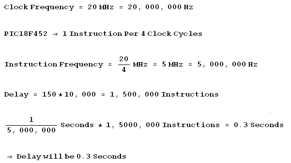
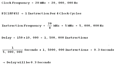
-Delay10KTCYx(150) delays the PIC 10K Instruction Cycles * 150 = 1,500,000
-Setting PORTA to 0x00 (Binary - 00000000) turns Bit zero off.
-Once again we see the 1,500,000 Instruction Cycle Delay.
Calculating The Delay
#include <p18f452.h>

                            #include <delays.h>
The p18f452.h include file gives us easy access to the different ports & registers that this PIC uses. Each different version of the PIC will have a respective include file (i.e. p18f455.h..etc).
The delays.h include file provides us with access to simple delay functions from the C18 Compiler library that we are using. We downloaded and installed this compiler suite in the previous PIC tutorial.
void main(void){
All ANSI C programs start with the main function. Since the PIC doesn't run on an operating system it is not necessary to return any value or pass any values to the main function. So we see
TRISA = 0x00;

                            PORTA = 0x00;
Inorder to use PORTA as an output we need to configure the the tri-state register on the PIC. Setting TRISA to 0x00 configures all of the bits on PORTA as outputs. This means we can set each pin on PORTA as we so desire to a logic 0 (0 volts) or logic 1 (5 volts). We then initialize PORTA to output all logic 0's.
    while(1){

                                    PORTA = 0x01;

                                    Delay10KTCYx(150);

                                    PORTA = 0x00;

                                    Delay10KTCYx(150);

                                }
This is where the program actually turns the LED off and on by toggling Bit 0 of PORTA between logic 0 and logic 1. The while loop runs the 4 lines of code forever.
-Setting PORTA to 0x01 (Binary - 00000001) turns Bit zero on.
-Delay10KTCYx(150) delays the PIC 10K Instruction Cycles * 150 = 1,500,000
-Setting PORTA to 0x00 (Binary - 00000000) turns Bit zero off.
-Once again we see the 1,500,000 Instruction Cycle Delay.
Calculating The Delay