Interrupt Theory
The interrupt theory will be split into three sections below. First, we'll take a look at why we need electronic interrupts in a Polling vs. Interrupts section, then we will explore the type of interrupt we are using on the PIC (there are many different types) for this tutorial and lastly we will look at what registers on the PIC need to be configured to use this interrupt.
Polling VS.
Interrupts
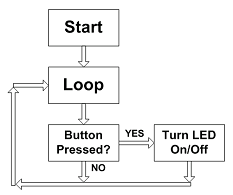
Polling For Input
The picture on the left hand side represents a normal program that checks if a button is pressed. If the button is pressed the LED state gets changed and then the program loops again to check if the button is pressed. This is the only purpose of the program, to check for a button press every microsecond. This is great if that's all we need to do, but what if we also want to check some sensor data every 2 miliseconds and update text on an LCD? Polling for data here becomes a burden because it messes up our timing and makes the processor execute a lot of extra instructions every loop.
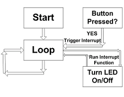
An Interrupt Trigger Input
If you look at the picture on the right, we see a similar but different flow. Instead of a single main loop, there's two loops. Like before there's a main loop of some code that goes forever, but there's also an external signal that is input to the loop (an interrupt trigger). When this signal gets hit, the main loop of executing code pauses, runs the interrupt function (called an interrupt service routine) and then returns to the main loop and does whatever it was doing before.
PIC External Interrupt
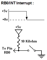
The type of hardware interrupt that this tutorial will use is called an interrupt-on-change. There are two types of 'changes' that we can set the interrupt for, either a rising edge change which would be +0v to +5v or a falling edge change which would be a +5v to +0v. We will be using the falling edge setting. So when the push button is pressed, the PIC's RB0 pin will change from +5v to +0v and a hardware interrupt will be triggered.
The interrupt theory will be split into three sections below. First, we'll take a look at why we need electronic interrupts in a Polling vs. Interrupts section, then we will explore the type of interrupt we are using on the PIC (there are many different types) for this tutorial and lastly we will look at what registers on the PIC need to be configured to use this interrupt.
Polling For Input
The picture on the left hand side represents a normal program that checks if a button is pressed. If the button is pressed the LED state gets changed and then the program loops again to check if the button is pressed. This is the only purpose of the program, to check for a button press every microsecond. This is great if that's all we need to do, but what if we also want to check some sensor data every 2 miliseconds and update text on an LCD? Polling for data here becomes a burden because it messes up our timing and makes the processor execute a lot of extra instructions every loop.
An Interrupt Trigger Input
If you look at the picture on the right, we see a similar but different flow. Instead of a single main loop, there's two loops. Like before there's a main loop of some code that goes forever, but there's also an external signal that is input to the loop (an interrupt trigger). When this signal gets hit, the main loop of executing code pauses, runs the interrupt function (called an interrupt service routine) and then returns to the main loop and does whatever it was doing before.
The type of hardware interrupt that this tutorial will use is called an interrupt-on-change. There are two types of 'changes' that we can set the interrupt for, either a rising edge change which would be +0v to +5v or a falling edge change which would be a +5v to +0v. We will be using the falling edge setting. So when the push button is pressed, the PIC's RB0 pin will change from +5v to +0v and a hardware interrupt will be triggered.