Hardware Design
Looking at the theory and proposed schematic is fun, but we need to actually build this thing and see it in action. Below are the steps that it takes to build the circuit on a breadboard.
Building The Circuit
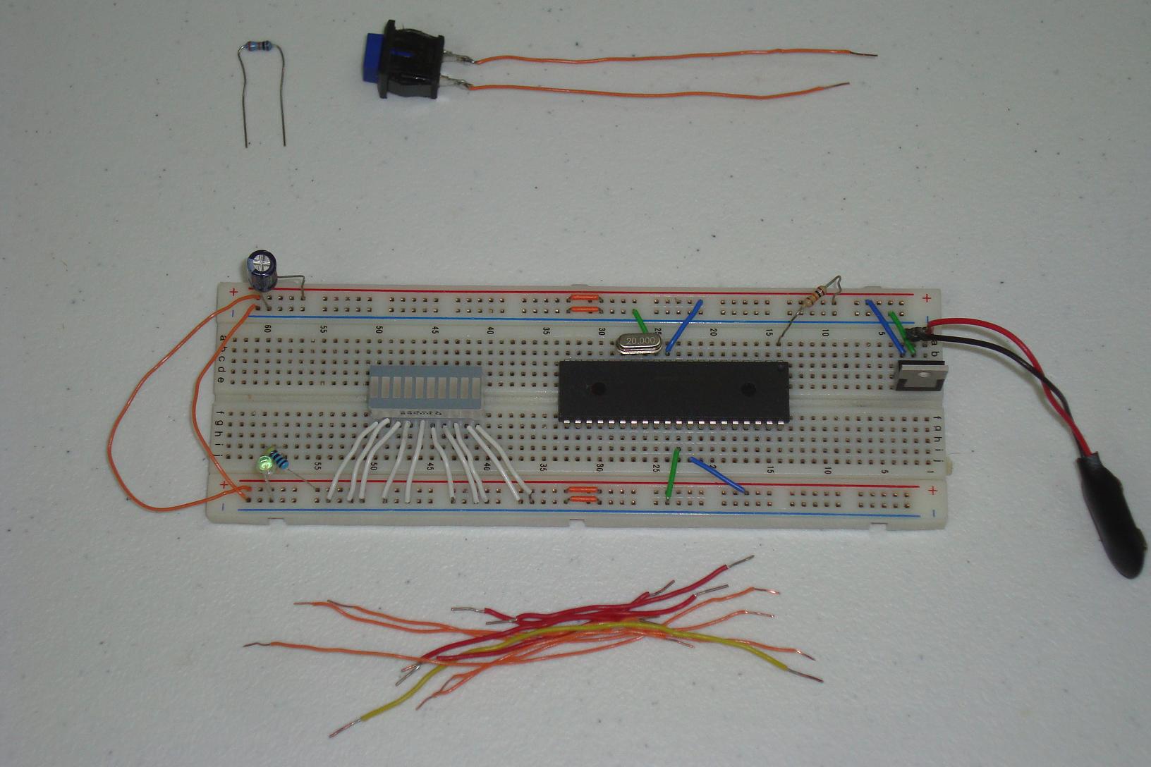
Get your parts together and follow the schematic. I build mine and in stages as you can see below...
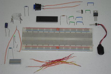
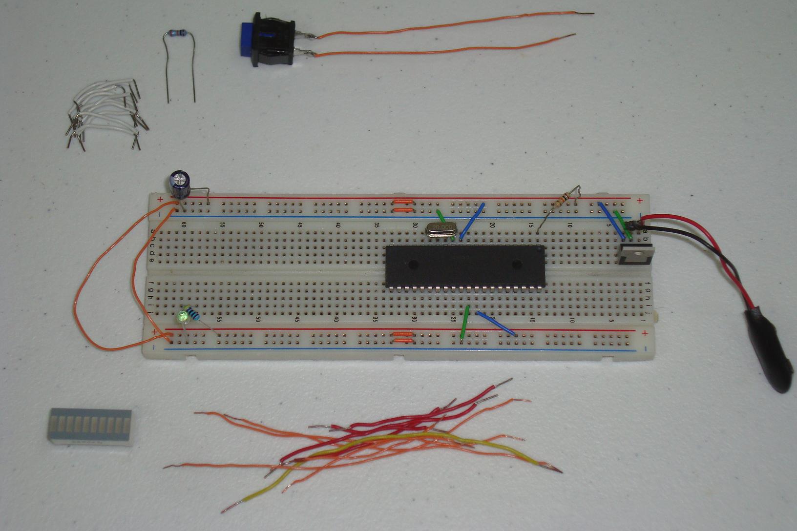
·First the power regulator circuit connected on the breadboard.
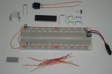
·The PIC microcontroller circuit comes next.
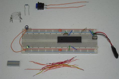
·I put the LED bar here. Depending on the length of your jumper wires, place it appropriately.

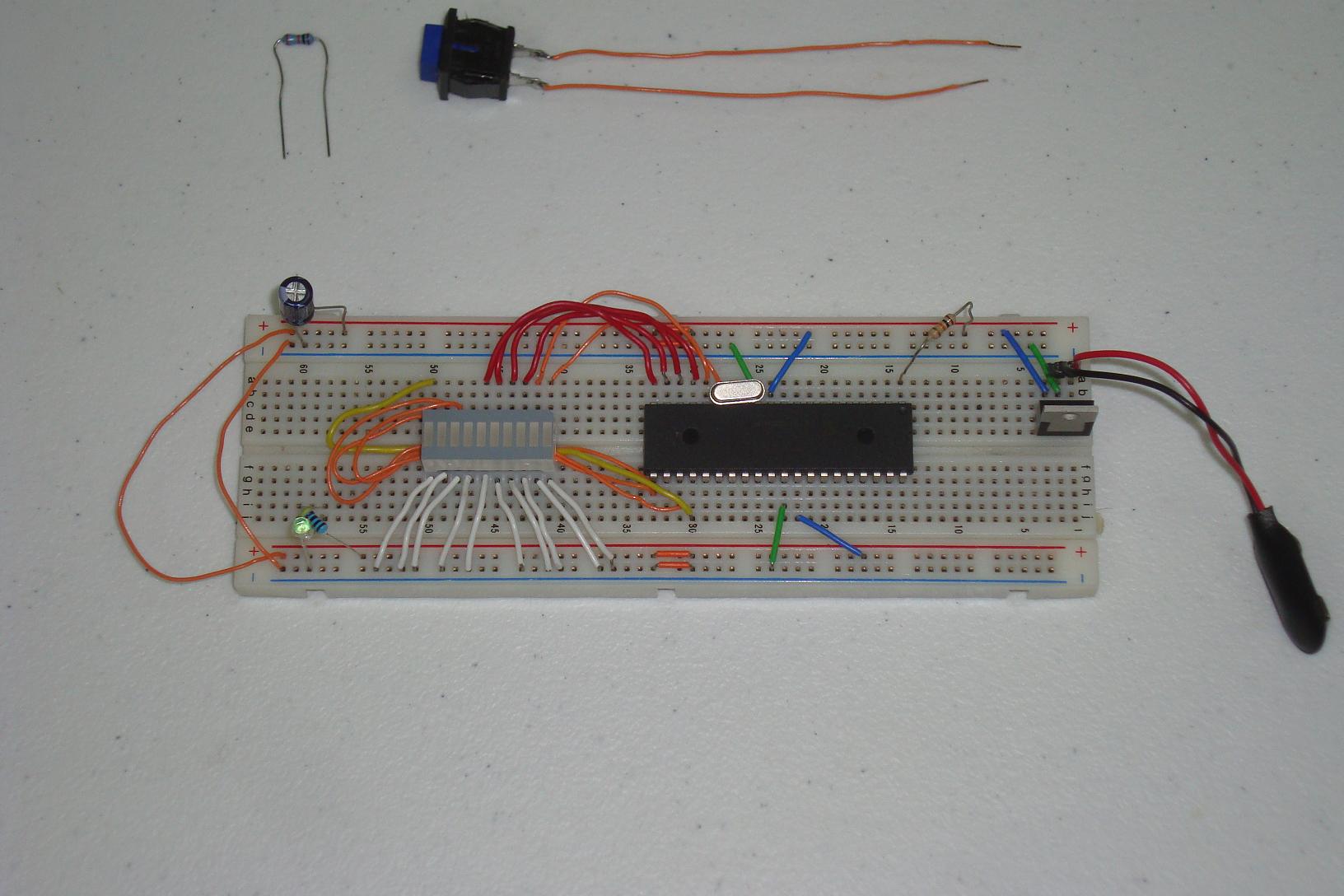
·One side of the LED bar is connected to ground. I used all white wires for that.
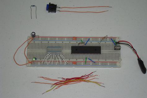
·Next the other side of the LED bar needs to be connected to the PIC's PORTC and PORTD.

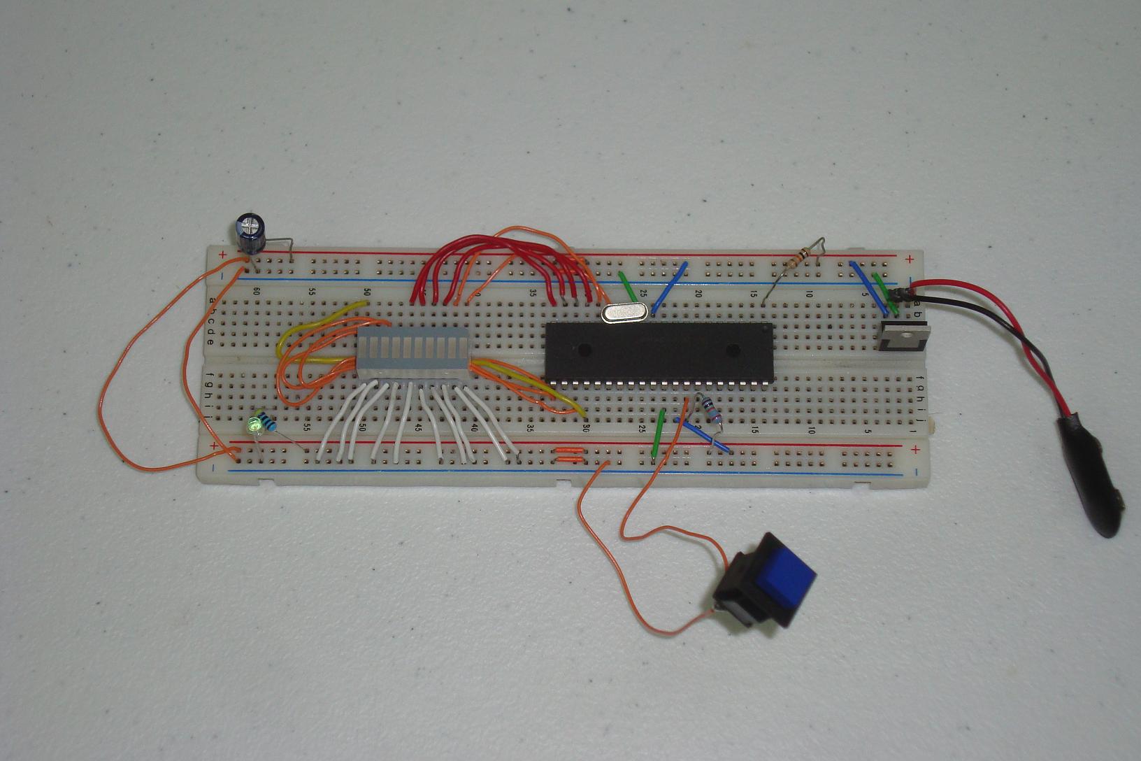
·Lastly, the push button and 10k pull-up resistor are added to RB0 on PORTB.
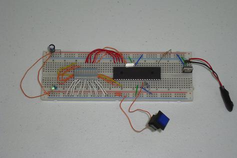
·The hardware has been built, now let's get the software loaded.
Looking at the theory and proposed schematic is fun, but we need to actually build this thing and see it in action. Below are the steps that it takes to build the circuit on a breadboard.
Building The Circuit
Get your parts together and follow the schematic. I build mine and in stages as you can see below...
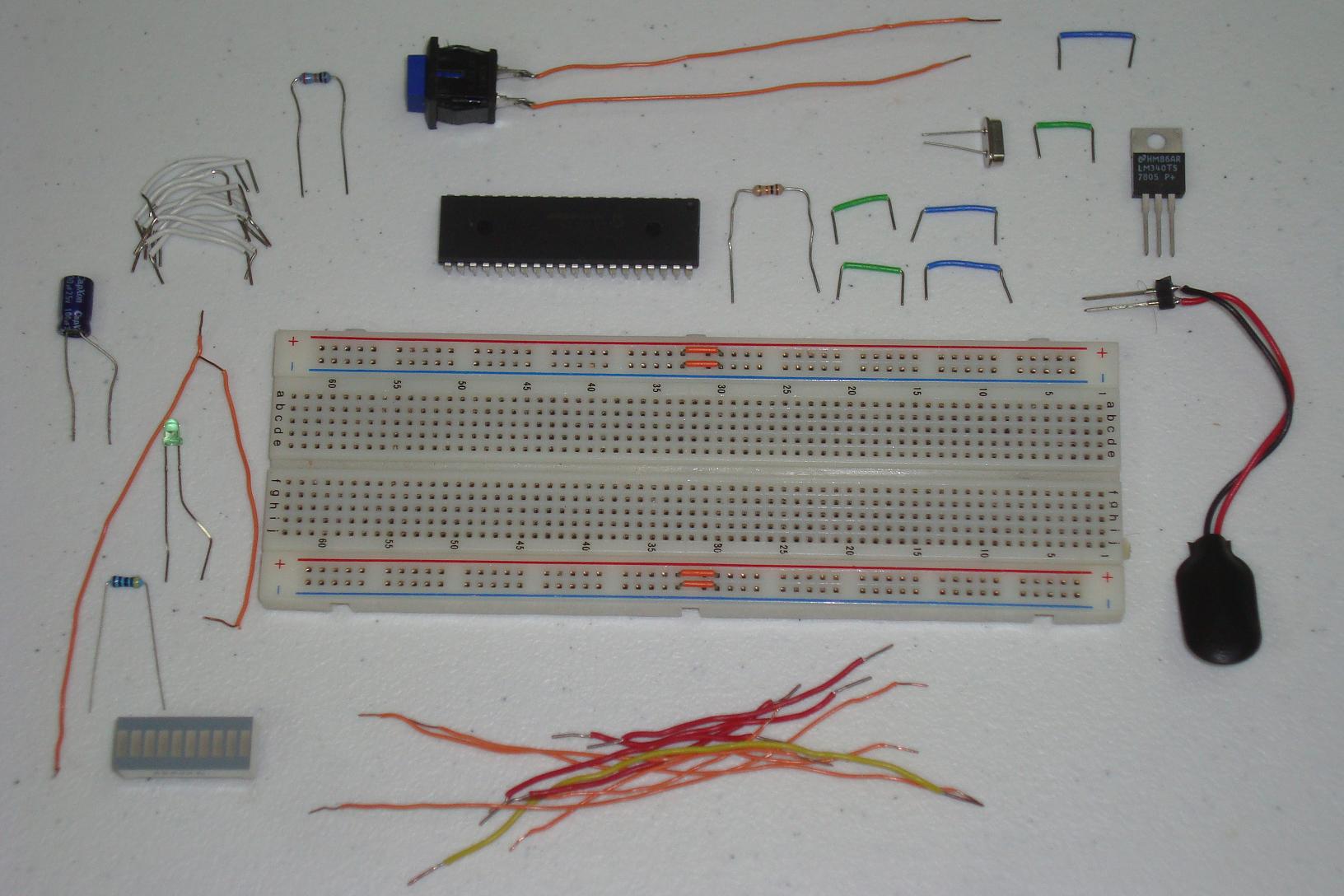
·First the power regulator circuit connected on the breadboard.

·The PIC microcontroller circuit comes next.
·I put the LED bar here. Depending on the length of your jumper wires, place it appropriately.
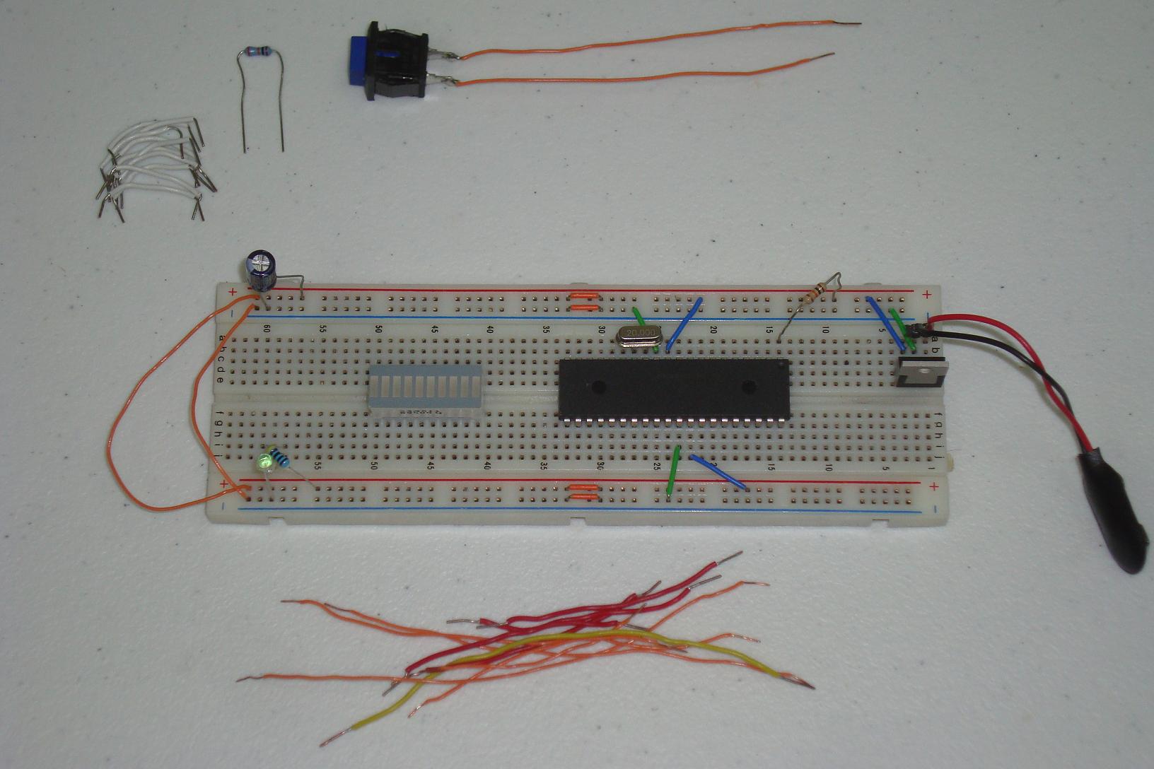
·One side of the LED bar is connected to ground. I used all white wires for that.
·Next the other side of the LED bar needs to be connected to the PIC's PORTC and PORTD.
·Lastly, the push button and 10k pull-up resistor are added to RB0 on PORTB.
·The hardware has been built, now let's get the software loaded.