Schematic Overview
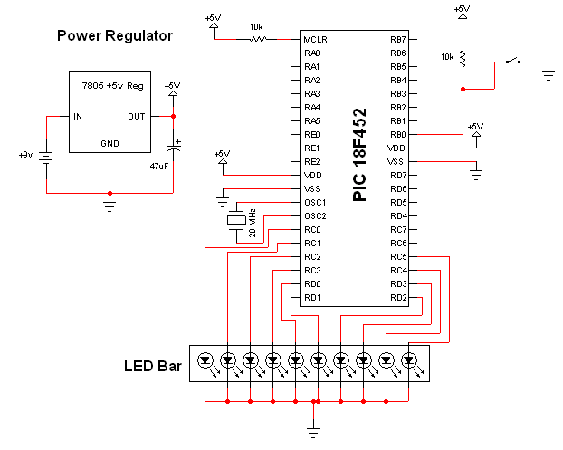
The schematic for this tutorial was kept as simple as possible so we could keep focus on what interrupts are and how we use them on the PIC. You can see the completed schematic for this project below. The main parts in the schematic are the 7805, 18F452 and LEDbar.
View Full Schematic
Schematic Specifics
Power Regulator
If you follow my projects and tutorials you'll recognize this circuit. It's an extremely simple and straight forward +5v regulator circuit with bypass capacitor.
Microcontroller Circuit
The microcontroller is connected to a SPST button, which is tied to ground on one side and pulled high via a pull-up resistor (to +5v) on the other side, which is also connected to PORTB RB0 on the PIC.
LED Bar
The LED Bar is a 10 LED horizontal bar. An LED will light up when the PIC sends an output signal from any of the pins (PORTC and PORTD) connected to the LED bar.