Schematic Overview
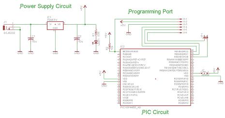
The schematic for this project is kept to be as simple as possible. There are definitely ways you could add more parts to build a more redunant power and programming port, but that would increase the size of the PCB, we're going for compact, yet functional here. The main parts in the schematic are the PIC 18F452, LM7805 and Power LED.
Eagle Schematic/Layout Files: PIC_DEV_BD.zip
View Large Schematic
Schematic Specifics
Power Regulator
The 7805 converts the input +9v down to a +5v output which powers the PIC. The PIC has two spots where it connects to power and ground, and there is a single 10kΩ resistor connected to the MCLR Pin1 of the pic that goes to power.
ICSP connection
ICSP is short for in-circuit serial programmer and this is the port used on almost every PIC microcontroller to load your program onto it. The PICKit3/PICKit2 have the same pinout as the connector seen above, the little dot on the PICKit3/PICKit2 tells you which connection is PIN1 or MCLR.
Power LED
A single LED on the board tells you when power is connected and flowing to the PIC 18F452. If this LED is on, you're good to go, if it's not, your power either isn't enough or is not connected properly.
The schematic for this project is kept to be as simple as possible. There are definitely ways you could add more parts to build a more redunant power and programming port, but that would increase the size of the PCB, we're going for compact, yet functional here. The main parts in the schematic are the PIC 18F452, LM7805 and Power LED.

View Large Schematic
Schematic Specifics
Power Regulator
The 7805 converts the input +9v down to a +5v output which powers the PIC. The PIC has two spots where it connects to power and ground, and there is a single 10kΩ resistor connected to the MCLR Pin1 of the pic that goes to power.
ICSP connection
ICSP is short for in-circuit serial programmer and this is the port used on almost every PIC microcontroller to load your program onto it. The PICKit3/PICKit2 have the same pinout as the connector seen above, the little dot on the PICKit3/PICKit2 tells you which connection is PIN1 or MCLR.
Power LED
A single LED on the board tells you when power is connected and flowing to the PIC 18F452. If this LED is on, you're good to go, if it's not, your power either isn't enough or is not connected properly.