CPLD -> LCD Interface Theory
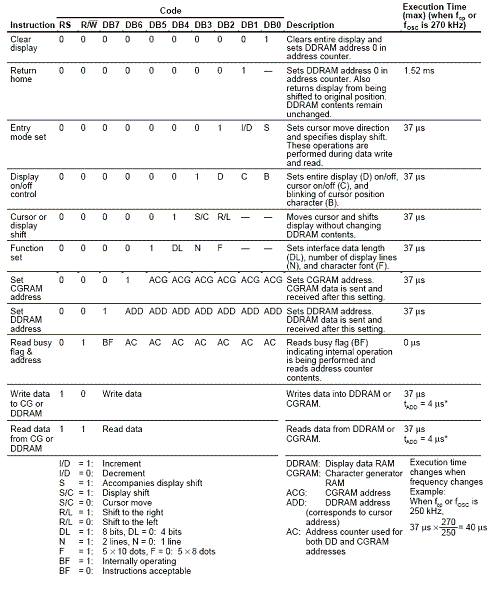
Luckily the interfacing is fairly straight forward with a FPGA to HD44780 bus. Our CPLD will not control the lcd directly instead it will send commands to the on-board lcd controller, the HD44780. All the commands that we can send (there are only 11) to the controller are listed out in this chart:
Click To Enlarge
Looking through the chart, there are two things to notice. (1) We can use either an 8-bit or 4-bit data bus for communication with the lcd interface. This is a great advantage because it lessens the amount of wires & i/o ports that we have to use. (2) We have to set it to display either 1 or 2 lines. These two things are done in the function set command.
Most of these commands are rarely used, as you can imagine printing the characters is what happens most with the lcd.
CPLD -> State Machine Logic
In order to send commands in a linear fashion in the CPLD we'll need to use a unique feature found in FPGA/CPLD design called the state machine.
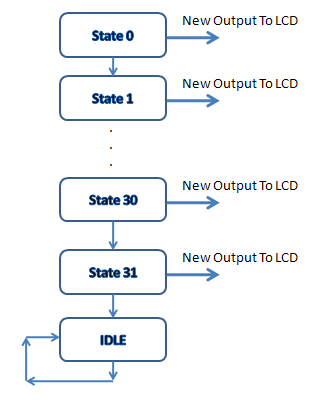
The image seen above represents a simple example of how the flow of the VHDL program will look. Each of 32 states will have a unique output that will either be a command to setup the LCD or a command to print a character. Typically two starts are needed to send a command to the FPGA since the enable line needs to be 'pulsed' before the LCD interface can accept any control or data input.
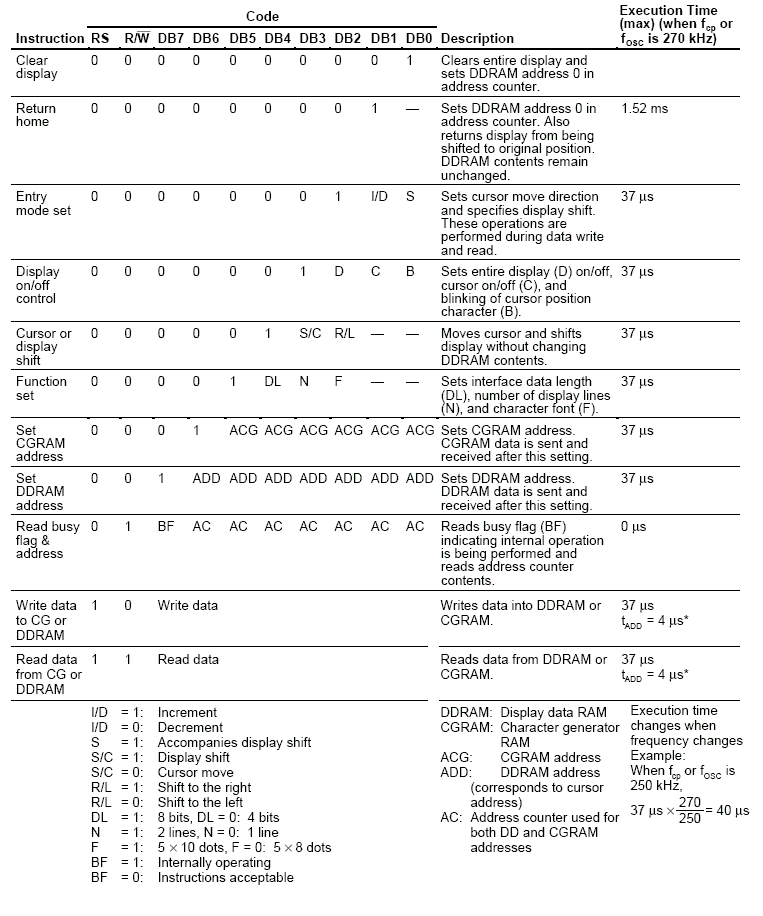
Luckily the interfacing is fairly straight forward with a FPGA to HD44780 bus. Our CPLD will not control the lcd directly instead it will send commands to the on-board lcd controller, the HD44780. All the commands that we can send (there are only 11) to the controller are listed out in this chart:
Click To Enlarge
Looking through the chart, there are two things to notice. (1) We can use either an 8-bit or 4-bit data bus for communication with the lcd interface. This is a great advantage because it lessens the amount of wires & i/o ports that we have to use. (2) We have to set it to display either 1 or 2 lines. These two things are done in the function set command.
Most of these commands are rarely used, as you can imagine printing the characters is what happens most with the lcd.
CPLD -> State Machine Logic
In order to send commands in a linear fashion in the CPLD we'll need to use a unique feature found in FPGA/CPLD design called the state machine.
The image seen above represents a simple example of how the flow of the VHDL program will look. Each of 32 states will have a unique output that will either be a command to setup the LCD or a command to print a character. Typically two starts are needed to send a command to the FPGA since the enable line needs to be 'pulsed' before the LCD interface can accept any control or data input.