Project Info
Author: Chris
Difficulty: Easy
Time Invested: 2 Hours
Prerequisites:
Take a look at the above
articles before continuing
to read this article.
Author: Chris
Difficulty: Easy
Time Invested: 2 Hours
Prerequisites:
Take a look at the above
articles before continuing
to read this article.
This article will show the process of choosing parts, building a schematic, connecting the hardware and writing the hardware description to control a HD44780 LCD interface and output a few characters to the 16x2 LCD screen. To make things a little easier, we'll use a familiar board, the CPLD Dev Board that I introduced a few years ago. It's dated but still a good learning platform!
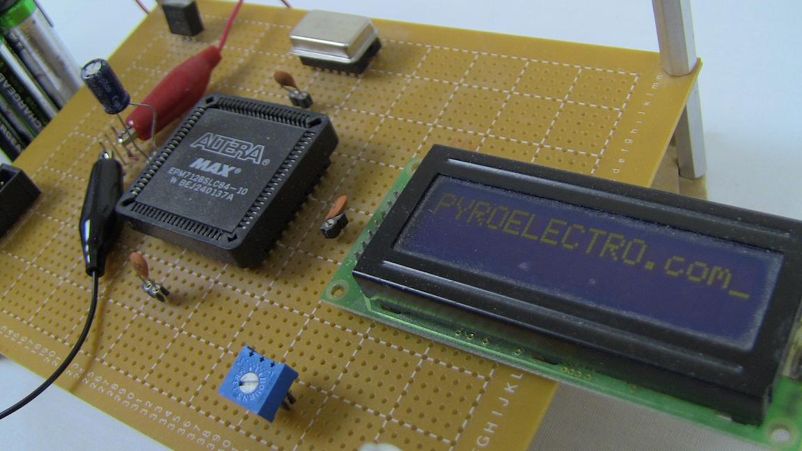
Purpose & Overview of this project
The goal of this project is to build a simple interface module for a CPLD/FPGA device to connect up and control a HD44780 LCD module. The module has a set of commands that tell it what to do, so our custom module inside the FPGA/CPLD will need to be able to craft these commands to display characters exactly as we want them to be displayed.
We will achieve this goal by first adding a 25.175 MHz clock signal input and then wire-wrapping the LCD module and a trimpot variable resistor to the already existing CPLD Dev Board. VHDL will be used to build the custom FPGA/CPLD module to interface with the HD44780 LCD.