Schematic Overview
The circuit for the Digital Tachometer/RPM Counter tutorial consists of only a few devices. Wire them up according to the following circuit diagram. The PIC I'm using is on a demonstration board, which means the clock, power and ground pins are already wired up so I didn't bother to include that on the schematic.
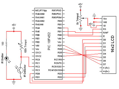
View Full Schematic
Schematic Specifics
IR Emit/Detect Circuit
This is the digital tachometer portion of circuit that will send +5v pulses to the RC2/CCP1 pin of the pic. The CCP module, specifically the capture module #1 on the PIC is located at this pin.
16x2 LCD Interface
This is the standard 16x2 character LCD and the interface consists of 8 bits of data, with 3 control signals. Power, Ground and Contrast are the last signals to wire up. The PIC sends commands to this 16x2 LCD over the control and data lines and the LCD does what it is told. The HD44780 system that this LCD uses is standarized and the datasheet is widely available.
The circuit for the Digital Tachometer/RPM Counter tutorial consists of only a few devices. Wire them up according to the following circuit diagram. The PIC I'm using is on a demonstration board, which means the clock, power and ground pins are already wired up so I didn't bother to include that on the schematic.
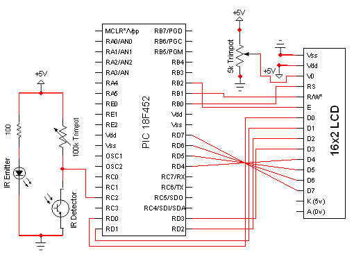
View Full Schematic
Schematic Specifics
IR Emit/Detect Circuit
This is the digital tachometer portion of circuit that will send +5v pulses to the RC2/CCP1 pin of the pic. The CCP module, specifically the capture module #1 on the PIC is located at this pin.
16x2 LCD Interface
This is the standard 16x2 character LCD and the interface consists of 8 bits of data, with 3 control signals. Power, Ground and Contrast are the last signals to wire up. The PIC sends commands to this 16x2 LCD over the control and data lines and the LCD does what it is told. The HD44780 system that this LCD uses is standarized and the datasheet is widely available.