An Overview Of The Build A Digital Tachometer/RPM Counter
The process of building this digital tachometer may have seemed quite easy, but the amount of previous theoretical knowledge and understanding of electronics is what makes it look so easy. The circuit is by no means complex, the programming can be a little daunting but still do-able and so overall this is a project any beginner can take on and come out successful. Please be mindful that this implementation is just a guide for one way of building a solution, it's not meant to be the best.
What To Do Now
The next step would be to use the information the IR photo-detector circuit tells you in a feedback loop to properly control a motor or perhaps the cpu fan. As with most projects or tutorials on there, the limit of where you can go is only with your imagination. This design was simple and to the point, but there is so much elbo room to improve on the design that it almost wouldn't make sense not to improve something if you're duplicating this project.
Conclusion
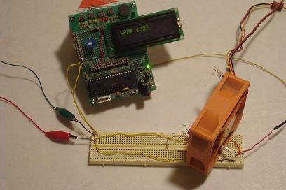
Building the digital tachometer came out successfully as we saw in the data & observations section. The video showed the circuit with a computer fan interrupting the emitter/detector circuit which sent rising edge signals of +5v to the microcontroller. The LCD output the proper value from the rpm counter corresponding to the fan's current speed and it was accurate! One additional thing I did do to verify, was capture the pulse frequency on an oscilloscope and make sure it matched up with the LCD's RPM data which it did. Just a way to double check.
If you have any further questions, I implore you...don't be shy, take a look at the forums or ask a question there. I check them out regularly and love getting comments & questions.
The process of building this digital tachometer may have seemed quite easy, but the amount of previous theoretical knowledge and understanding of electronics is what makes it look so easy. The circuit is by no means complex, the programming can be a little daunting but still do-able and so overall this is a project any beginner can take on and come out successful. Please be mindful that this implementation is just a guide for one way of building a solution, it's not meant to be the best.
What To Do Now
The next step would be to use the information the IR photo-detector circuit tells you in a feedback loop to properly control a motor or perhaps the cpu fan. As with most projects or tutorials on there, the limit of where you can go is only with your imagination. This design was simple and to the point, but there is so much elbo room to improve on the design that it almost wouldn't make sense not to improve something if you're duplicating this project.
Conclusion
Building the digital tachometer came out successfully as we saw in the data & observations section. The video showed the circuit with a computer fan interrupting the emitter/detector circuit which sent rising edge signals of +5v to the microcontroller. The LCD output the proper value from the rpm counter corresponding to the fan's current speed and it was accurate! One additional thing I did do to verify, was capture the pulse frequency on an oscilloscope and make sure it matched up with the LCD's RPM data which it did. Just a way to double check.
If you have any further questions, I implore you...don't be shy, take a look at the forums or ask a question there. I check them out regularly and love getting comments & questions.