Hardware Design
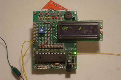
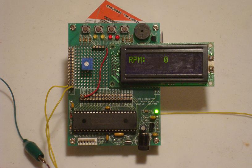
The schematic should be pretty clear, wire up the LCD and then wire up the IR circuit to make the digital tachometer. Since I'm building off of a demonstration board, I'll attach the LCD to it and wire-wrap the LCD pins to the corresponding PIC pins. The picture below shows the finished product with the software running:
The IR Emitter/Detector Circuit
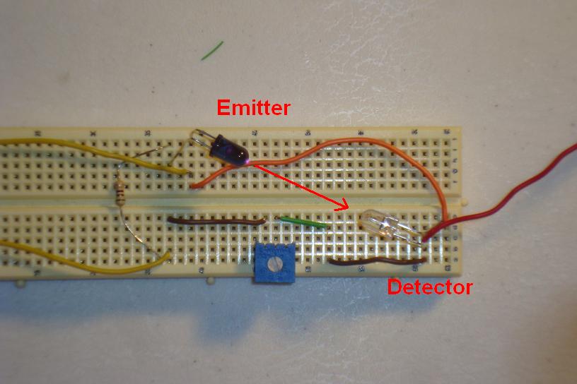
Similarly, this part of the circuit needs to be wired up. Straight from the schematic I put everything on a bread board. Only 1 data wire from this board needs to connect to the PIC on pin RC2/CCP1. However, since both systems run off of +5v, I also connected the +5v power and Ground bus to the IR circuit.

A Close-Up View
To get a better look at exactly how the circuit will get interrupted, here's a picture with the fan inbetween the IR circuit:
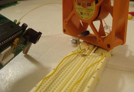
From that picture you can see how the blades will interrupt the IR emitter as the fan spins. Now that we have everything wired up and setup, let's take a look at the software and get it programmed onto the PIC so we can see this baby in action!
The schematic should be pretty clear, wire up the LCD and then wire up the IR circuit to make the digital tachometer. Since I'm building off of a demonstration board, I'll attach the LCD to it and wire-wrap the LCD pins to the corresponding PIC pins. The picture below shows the finished product with the software running:
The IR Emitter/Detector Circuit
Similarly, this part of the circuit needs to be wired up. Straight from the schematic I put everything on a bread board. Only 1 data wire from this board needs to connect to the PIC on pin RC2/CCP1. However, since both systems run off of +5v, I also connected the +5v power and Ground bus to the IR circuit.
A Close-Up View
To get a better look at exactly how the circuit will get interrupted, here's a picture with the fan inbetween the IR circuit:

From that picture you can see how the blades will interrupt the IR emitter as the fan spins. Now that we have everything wired up and setup, let's take a look at the software and get it programmed onto the PIC so we can see this baby in action!