The Schematic
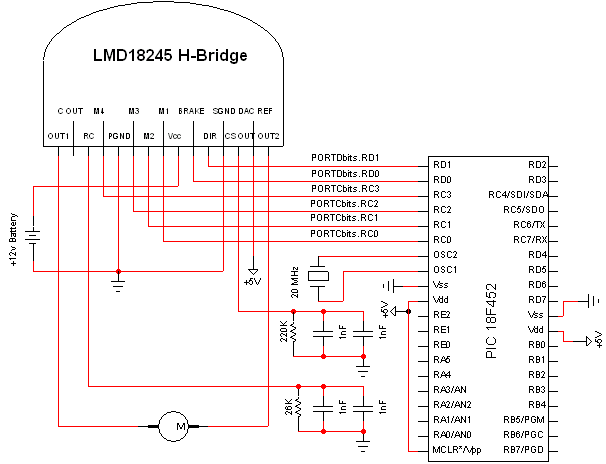
The schematic seen below uses all the hardware components we've seen up to this point. If you're following along with this tutorial be sure to follow it exactly as seen below. If you don't have 220k resistor use the closest value you can find near it, preferrably higher.
Click to Enlarge:

Components are labeled to the best of my ability. Parts hooked up to the PIC are minial and it should be recognized that this experiment actually uses the Olimex P-40 Development board and not a bare bones PIC layout as seen in the schematic. However if you choose to follow the schematic exactly it will work the same as it would with the development board, provided of course that the software is preprogrammed onto the PIC.
6 Important Pins
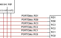
Taking a closer look at the schematic we see that only 6 pins are connected PIC18F452 -> LMD18245.
These pins are:
-Direction
-Brake
-M4
-M3
-M2
-M1
Each pin will carry either a digital 0 or 1 and this is what will control the motor. In the next section with the software we will get a better look at exactly how we can control the motor using these 6 pins.
The schematic seen below uses all the hardware components we've seen up to this point. If you're following along with this tutorial be sure to follow it exactly as seen below. If you don't have 220k resistor use the closest value you can find near it, preferrably higher.
Click to Enlarge:
Components are labeled to the best of my ability. Parts hooked up to the PIC are minial and it should be recognized that this experiment actually uses the Olimex P-40 Development board and not a bare bones PIC layout as seen in the schematic. However if you choose to follow the schematic exactly it will work the same as it would with the development board, provided of course that the software is preprogrammed onto the PIC.
6 Important Pins
Taking a closer look at the schematic we see that only 6 pins are connected PIC18F452 -> LMD18245.
These pins are:
-Direction
-Brake
-M4
-M3
-M2
-M1
Each pin will carry either a digital 0 or 1 and this is what will control the motor. In the next section with the software we will get a better look at exactly how we can control the motor using these 6 pins.