The H-Bridge
The original concept of the H-Bridge was being able to control the direction a motor was going. Forward or backward. This was achieved by managing current flow through circuit elements called transistors. The formation looks like an H and that's where it gets the name H-Bridge. Here is what it looks like:
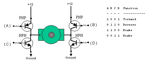
The picture above illustrates the 4 base cases that we can get out of the simple version of an H-Bridge. The two cases that interest us are when A & D are both 1 and when B & C are both 1.
When A & D are 1 current from the battery will flow from point A through the motor to D's ground. However for the case when B & C are both 1, current will flow in the opposite direction from B through the motor to C's ground.
LMD18245
To the right you'll see a sample of what the H-Bridge we'll be working with looks like with each pin labeled. For a complete description of what each pin does check out the datasheet at national.com.
For now we'll take a look at a unique feature that the LMD182xx series of H-Bridges offers us. It is called 'current sensing'. This is part of what the CS pin has to offer us.
H-Bridge Current Sensing
This feature allows us to limit the maximum amount of current that the motors can use. The motor we are using for this tutorial has a stall current of 80mA and an idle current of 60mA. This means inorder for the motor to even start turning it must initially be given a current of 80mA.
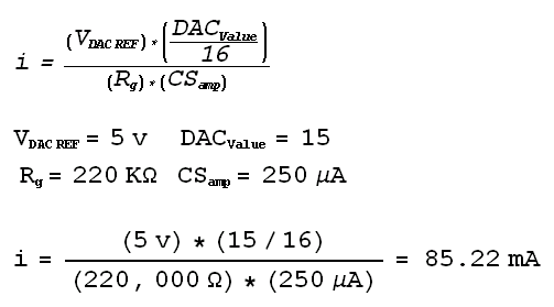 Using this formula we can now define the max current. In the above example we see a
max current of 85.22mA is allowed. Rg is the component that we can change to achieve that max current value. Then for varying speed We step the DACvalue down -1 at
a time, so that when the DACvalue is 8 the motor will run at half full speed.
Using this formula we can now define the max current. In the above example we see a
max current of 85.22mA is allowed. Rg is the component that we can change to achieve that max current value. Then for varying speed We step the DACvalue down -1 at
a time, so that when the DACvalue is 8 the motor will run at half full speed.
Varying DC Motor Speed
For another example. Say we want the motor to run at half speed and not full speed like we see above. You keep all the values the same in the given formula, change the DACvalue = 7/15. Calculate and you find max output current = 40mA.
The original concept of the H-Bridge was being able to control the direction a motor was going. Forward or backward. This was achieved by managing current flow through circuit elements called transistors. The formation looks like an H and that's where it gets the name H-Bridge. Here is what it looks like:
The picture above illustrates the 4 base cases that we can get out of the simple version of an H-Bridge. The two cases that interest us are when A & D are both 1 and when B & C are both 1.
When A & D are 1 current from the battery will flow from point A through the motor to D's ground. However for the case when B & C are both 1, current will flow in the opposite direction from B through the motor to C's ground.
LMD18245 Pinout
To the right you'll see a sample of what the H-Bridge we'll be working with looks like with each pin labeled. For a complete description of what each pin does check out the datasheet at national.com.
For now we'll take a look at a unique feature that the LMD182xx series of H-Bridges offers us. It is called 'current sensing'. This is part of what the CS pin has to offer us.
H-Bridge Current Sensing
This feature allows us to limit the maximum amount of current that the motors can use. The motor we are using for this tutorial has a stall current of 80mA and an idle current of 60mA. This means inorder for the motor to even start turning it must initially be given a current of 80mA.
Using this formula we can now define the max current. In the above example we see a
max current of 85.22mA is allowed. Rg is the component that we can change to achieve that max current value. Then for varying speed We step the DACvalue down -1 at
a time, so that when the DACvalue is 8 the motor will run at half full speed.Varying DC Motor Speed
For another example. Say we want the motor to run at half speed and not full speed like we see above. You keep all the values the same in the given formula, change the DACvalue = 7/15. Calculate and you find max output current = 40mA.