Schematic Overview
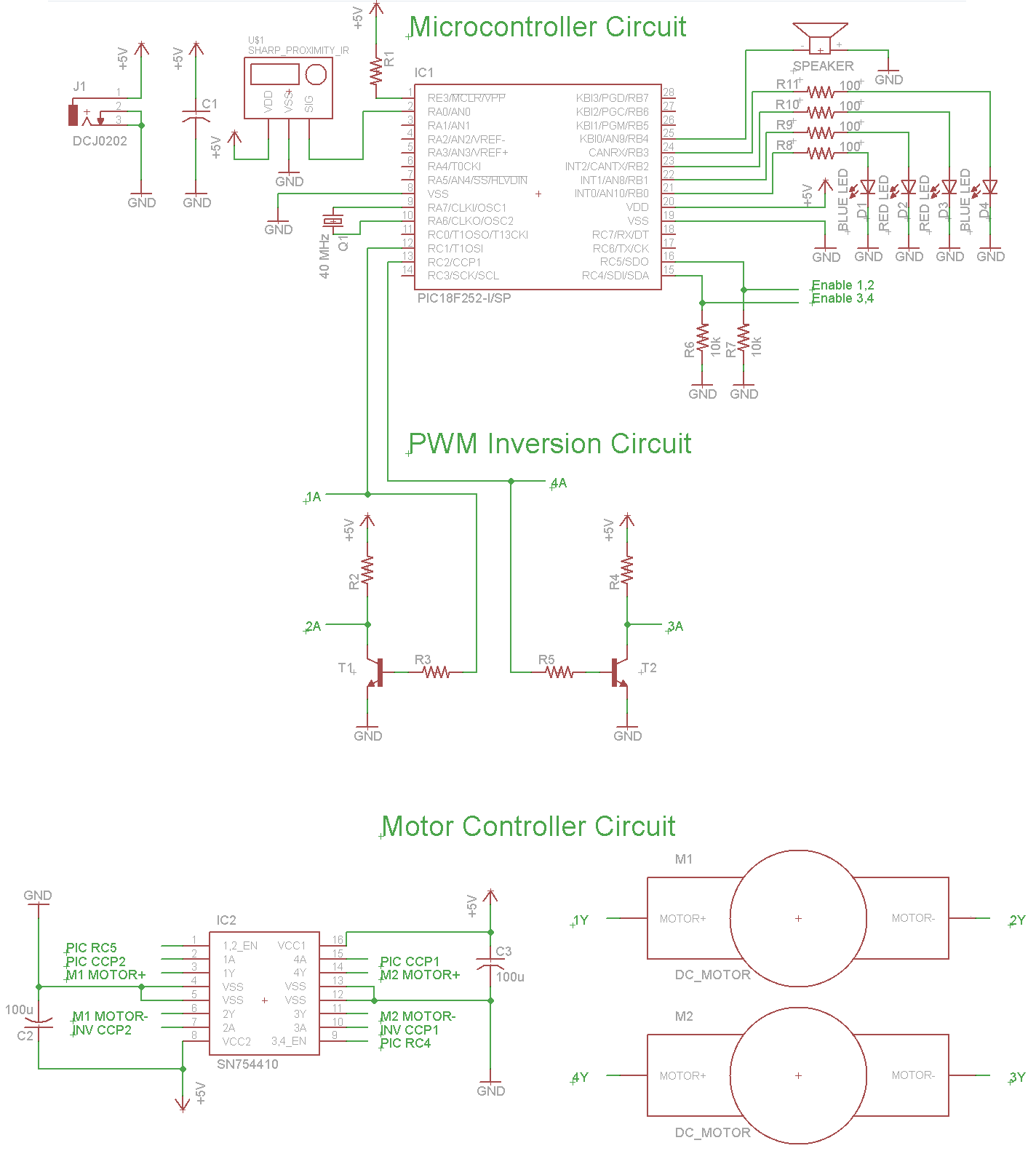
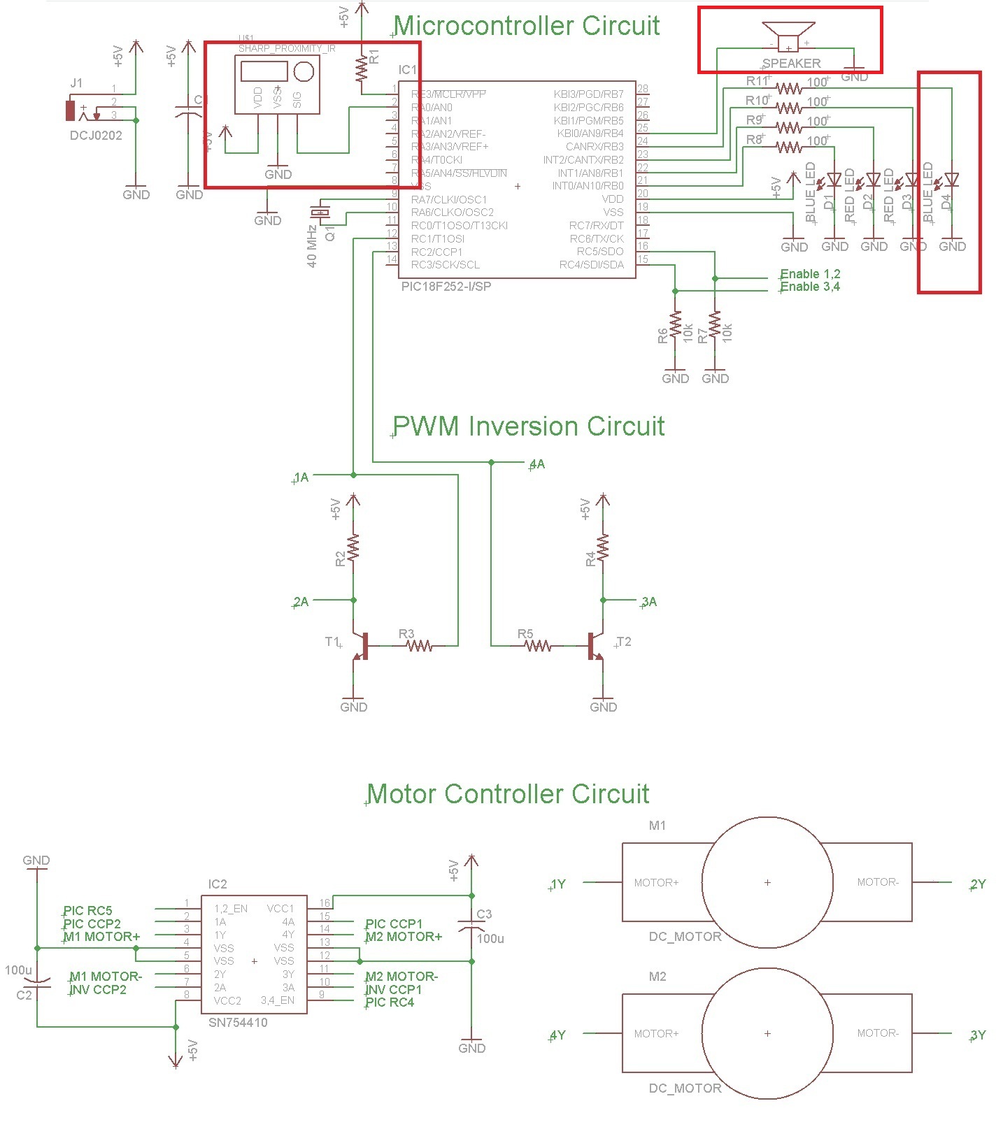
The Building A Robot: Proximity Sensor circuit can be seen below. Three red boxes show the additions to the circuit that we already built in Part 2: Motor Control. The new parts used and seen in the schematic below are the GP2Y0A21YK IR Sensor, Headphone Speaker and some LEDs.

View Full Schematic View Highlighted Schematic
Schematic Specifics
Infrared Proximity Sensor
The analog voltage (between +3.5v to +0.0v) is input into the PIC's AN0, Pin 1 which is the analog to digital converter on the PIC. This means the PIC can then convert that analog output into a digital integer that we can evaluate and use it to make intelligent decisions.
Warning Speaker
Just for fun, we'll add a headphone speaker so that the robot can 'scream' to warn off anything that gets too close to it. This really just means a little extra software, and it's a fun way to give some extra output that humans definitely understand.
Red & Blue LEDs
We'll also grab some LEDs from our assorted LEDs bag and put them into the circuit to give us feedback. Red LEDs will turn on when the proximity sensor detects something that is 'too close for comfort' and blue LEDs will represent when the robot is happy.
The Building A Robot: Proximity Sensor circuit can be seen below. Three red boxes show the additions to the circuit that we already built in Part 2: Motor Control. The new parts used and seen in the schematic below are the GP2Y0A21YK IR Sensor, Headphone Speaker and some LEDs.
View Full Schematic View Highlighted Schematic
Schematic Specifics
Infrared Proximity Sensor
The analog voltage (between +3.5v to +0.0v) is input into the PIC's AN0, Pin 1 which is the analog to digital converter on the PIC. This means the PIC can then convert that analog output into a digital integer that we can evaluate and use it to make intelligent decisions.
Warning Speaker
Just for fun, we'll add a headphone speaker so that the robot can 'scream' to warn off anything that gets too close to it. This really just means a little extra software, and it's a fun way to give some extra output that humans definitely understand.
Red & Blue LEDs
We'll also grab some LEDs from our assorted LEDs bag and put them into the circuit to give us feedback. Red LEDs will turn on when the proximity sensor detects something that is 'too close for comfort' and blue LEDs will represent when the robot is happy.