Project Info
Author: Chris
Difficulty: Easy
Time Invested: 2 Hours
Prerequisites:
Take a look at the above
articles before continuing
to read this article.
Author: Chris
Difficulty: Easy
Time Invested: 2 Hours
Prerequisites:
Take a look at the above
articles before continuing
to read this article.
In this article we will build an example system and use the basic tilt sensor as an input into a microcontroller. The microcontroller will read the data input from the tilt sensor and act accordingly to output the current state of the tilt sensor. Everything will be done on a breadboard to show how easy it is to assemble and use the system.
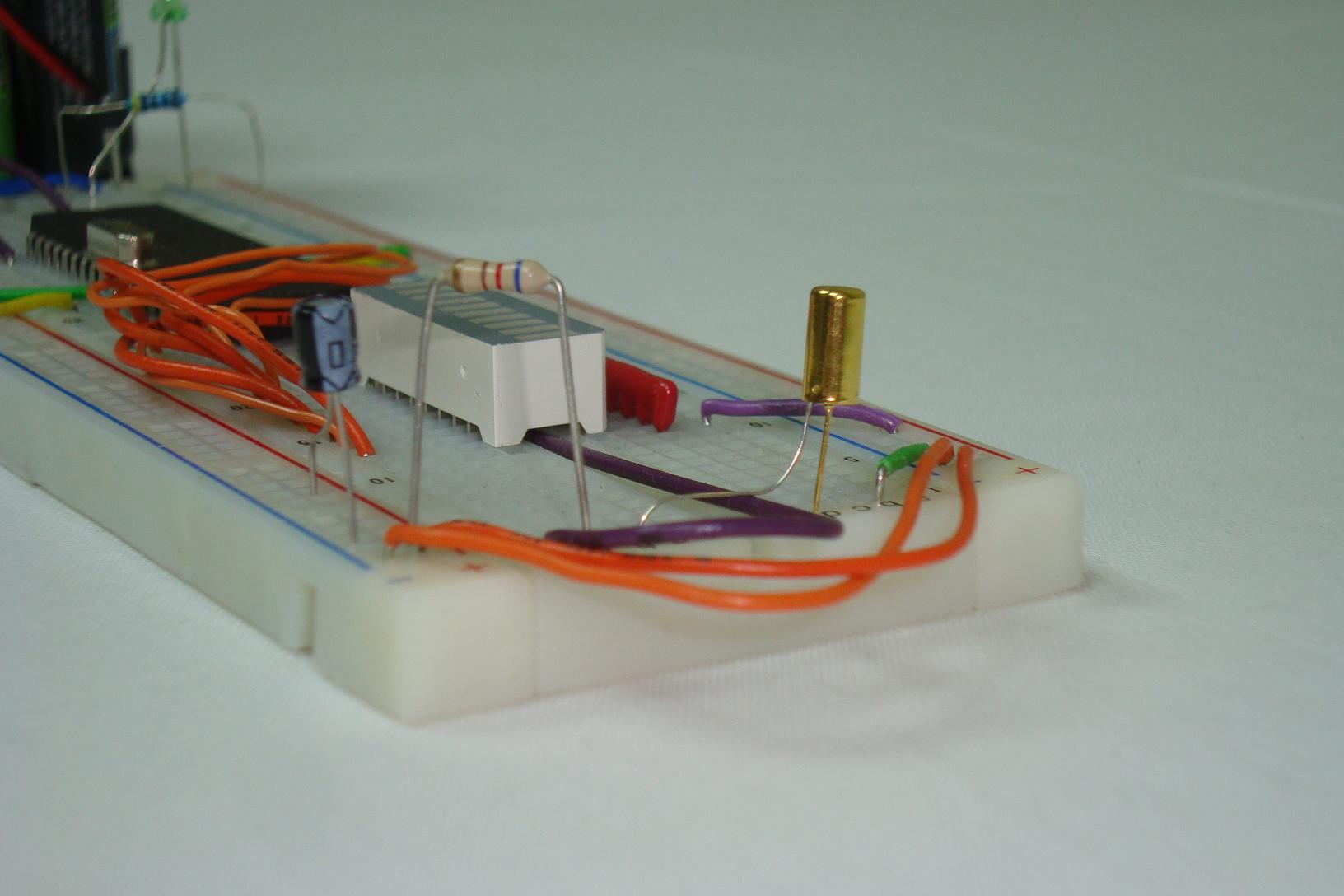
Purpose & Overview of this project
The goal of this project is to create a system that senses when the tilt sensor is tilted and halts the currently running firmware program. This will be done by making the tilt sensor act like a standard push button switch. One side will be connected to +5v and the other side to ground. These two states will be detected by the firmware in the microcontroller and then the proper output will occur.
To build this system we will use a PIC 18F452 microcontroller to take input from the basic tilt sensor and give output to 8 LEDs on an LED Bar. The firmware should run a simple knight-rider program on the LEDs and when a tilt is detected the program should halt until the system is no longer being tilted, then the program should resume as if nothing had occured.