Schematic Overview
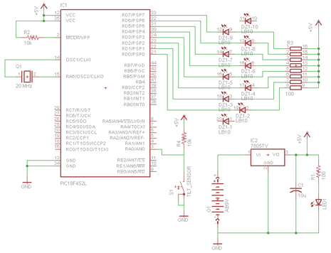
The schematic for this project has been kept super simple with very few parts keeping the total cost very low and assembly time low. The main parts in the schematic are the PIC 18F452, Tilt Sensor and LED Bar.
View Full Schematic
Schematic Specifics
Power Regulator
The power regulation circuit is in the lower right corner. It consists of the battery, a 7805, a capacitor and a resistor+led power led circuit, which lets you know power is on.
Tilt Sensor Circuit
The tilt sensor circuit is connected to the PIC's input at PORTA's RA0. It is pulled high to +5v when tilted and when not tilted, it acts like a button that has been pushed, connecting RA0 to ground.
LED Output Circuit
The LED output bar actually has 10 LEDs, however only 8 are connected since PORTD only has 8 output pins. You could use other ports to get all 10 LEDs lit up, but I felt 8 LEDs was enough to get the point across for this project.
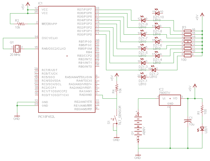