The Theory
The theory for this project is based upon the 3 main components of the schematic described in the previous page. Below I will run through the theory of how they work with some better illustrations to hammer the theory into your brain.
IR Emitter & Phototransistor Theory
The IR Emitter LED (D2) send outs IR light and the Phototransistor (Q6) receives IR light from the reflected surface. From high school we learned that white will reflect all colors while black will absorb them. So when the LED emits IR onto white, the Phototransistor is turned on and sends a voltage signal to Q1. When light is reflected off of black color the Phototransistor (Q6) is then turned off and no signal is sent
Looking At The Motor Circuit
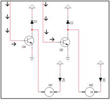
The motors are turned on when transistors Q4 or Q5 are switched on with a positive voltage. This happens in one of two cases. When black color is sensed, the circuit switches Q4 off and Q5 on. When white color is sensed the case is reversed with Q4 on and Q5 off. This means the motors are never actually on at the same time and the illusion of driving forward is created by quick back-and-forth movements
Working The Brains
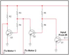
This circuit combines the Motor circuit and the IR Sensor Circuit. Using 3 2N2222's and some resistors a circuit is built that interprets the two cases. When white color is detected Q1 is turned on, which turns off Q2 and Q3 on. In the opposite case, when black color is detected Q1 is turned off, which means Q2 remains on and Q3 off. Understanding this circuit might take a few minutes staring at the schematic, it is a little complicated.
The theory for this project is based upon the 3 main components of the schematic described in the previous page. Below I will run through the theory of how they work with some better illustrations to hammer the theory into your brain.
IR Emitter & Phototransistor Theory
The IR Emitter LED (D2) send outs IR light and the Phototransistor (Q6) receives IR light from the reflected surface. From high school we learned that white will reflect all colors while black will absorb them. So when the LED emits IR onto white, the Phototransistor is turned on and sends a voltage signal to Q1. When light is reflected off of black color the Phototransistor (Q6) is then turned off and no signal is sent
Looking At The Motor Circuit
The motors are turned on when transistors Q4 or Q5 are switched on with a positive voltage. This happens in one of two cases. When black color is sensed, the circuit switches Q4 off and Q5 on. When white color is sensed the case is reversed with Q4 on and Q5 off. This means the motors are never actually on at the same time and the illusion of driving forward is created by quick back-and-forth movements
Working The Brains
This circuit combines the Motor circuit and the IR Sensor Circuit. Using 3 2N2222's and some resistors a circuit is built that interprets the two cases. When white color is detected Q1 is turned on, which turns off Q2 and Q3 on. In the opposite case, when black color is detected Q1 is turned off, which means Q2 remains on and Q3 off. Understanding this circuit might take a few minutes staring at the schematic, it is a little complicated.