Schematic Overview
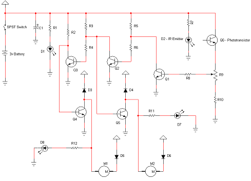
The Schematic has three main parts to it. The Sensor Circuitry where the accelerometer is wired up to the A/D converters. The second part is the power circuit where we have the On/Off switch, the 3.7v battery & +5v 7805 Voltage Regualtor. The 3rd part of the circuit is the 3 7-Segment LEDs.
View Full Schematic
Schematic Specifics
Motor Circuit
The motor circuit controls the motors depending on the sensor data that comes in through the 'analog brain' circuit. The two motors are 3v and can move moderatley fast. The diode that connects the motors to the battery reduces the voltage at the motors which slows them down a little bit.
IR Sensor Circuit
The IR Emitter LED and Phototransistor are used for sensing white or black color. The LED emits IR light and the phototransistor receives IR light. Together they work well at see what type of light if any is reflected from a surface.
Analog Brain Circuit
This part of the circuit connects the sensor circuit and the motor circuit together so that the robot can do its job. A little ASIC logic is used to transfer incoming sensor signals into which motor should be turned on and when.
Schematic Parts Reference:
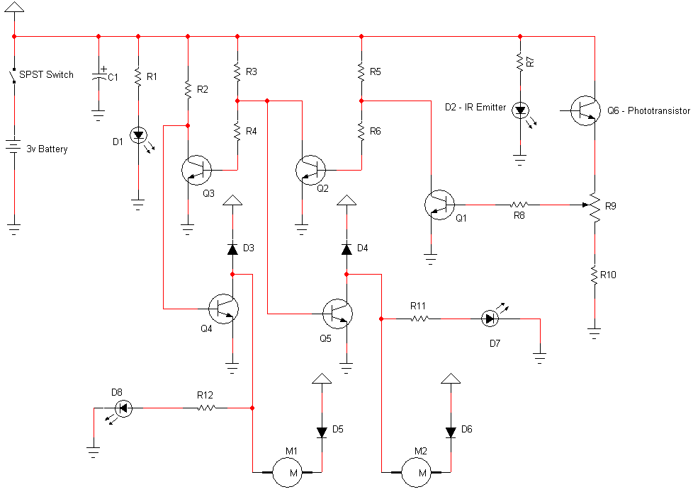
| Schematic Name | Part Name | Value/Type |
| R1 | Resistor | 330Ω |
| R2 | Resistor | 360Ω |
| R3 | Resistor | 360Ω |
| R4 | Resistor | 1500Ω |
| R5 | Resistor | 10000Ω |
| R6 | Resistor | 10000Ω |
| R7 | Resistor | 15Ω |
| R8 | Resistor | 10000Ω |
| R9 | Resistor | 5000Ω |
| R10 | Resistor | 10000Ω |
| R11 | Resistor | 150Ω |
| R12 | Resistor | 150Ω |
| D1 | Diode | LED-Red (5mm) |
| D2 | Diode | LED-IR Emitter (5mm) |
| D3 | Diode | 1N4001 |
| D4 | Diode | 1N4001 |
| D5 | Diode | 1N4001 |
| D6 | Diode | 1N4001 |
| D7 | Diode | LED-Green (3mm) |
| D8 | Diode | LED-Green (3mm) |
| Q1 | Transistor | 2N2222 |
| Q2 | Transistor | 2N2222 |
| Q3 | Transistor | 2N2222 |
| Q4 | Transistor | TIP120 |
| Q5 | Transistor | TIP120 |
| Q6 | Transistor | IR Phototransistor |
| C1 | Capacitor | 47μF |