Schematic Overview
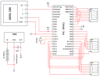
The Schematic has three main parts to it. The Sensor Circuitry where the accelerometer is wired up to the A/D converters. The second part is the power circuit where we have the On/Off switch, the 9v battery & +5v 7805 Voltage Regualtor. The 3rd part of the circuit is the 3 7-Segment LEDs.

View Full Schematic
Schematic Specifics
Power Circuit
The power circuit is a 9v Battery hooked up to the LM7805 with a 10uF capacitor wired to output & ground of the LM7805 to keep a steady 5v DC.
Sensor Circuit
The sensor is very simply wired with one wire from the Y-axis measurement spot to the AN0 port on the PIC. This is an analog input port and we'll use it as such. The other pins on the sensor aren't used, aside from Vcc & Gnd.
7-Segment LEDs
The wiring of the 3 7-Segment LED displays may seem somewhat random. The reason it looks strange is because I wrote the software and wired everything up before drawing out a proper schematic. This made my schematic drawing look pretty strange but the software and the actualy wiring very straight forward.
The Schematic has three main parts to it. The Sensor Circuitry where the accelerometer is wired up to the A/D converters. The second part is the power circuit where we have the On/Off switch, the 9v battery & +5v 7805 Voltage Regualtor. The 3rd part of the circuit is the 3 7-Segment LEDs.

View Full Schematic
Schematic Specifics
Power Circuit
The power circuit is a 9v Battery hooked up to the LM7805 with a 10uF capacitor wired to output & ground of the LM7805 to keep a steady 5v DC.
Sensor Circuit
The sensor is very simply wired with one wire from the Y-axis measurement spot to the AN0 port on the PIC. This is an analog input port and we'll use it as such. The other pins on the sensor aren't used, aside from Vcc & Gnd.
7-Segment LEDs
The wiring of the 3 7-Segment LED displays may seem somewhat random. The reason it looks strange is because I wrote the software and wired everything up before drawing out a proper schematic. This made my schematic drawing look pretty strange but the software and the actualy wiring very straight forward.