Hardware Design
Now that we've seen the schematic and a little bit of the theory let's take a look at the step-by-step process for building your personal g-force meter.
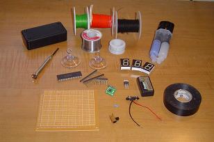
Step (1) - Gather All The Parts Previously Mentioned»
Step (2) - Clear Out The Insides Of The Plastic Enclosure»

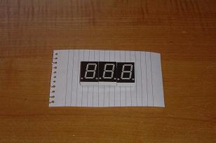
Step (3) - Map The Pinout Of The 7-Seg LEDs On a Piece Of Paper»
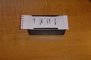
Step (4) - Drill Tiny Holes For Each Pin Of The 7-Seg LEDs»
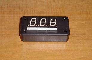
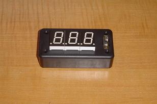
Step (5) - E-poxy the LEDs Onto The Enclosure»
Step (6) - Drill A Hole For The On/Off Switch & E-poxy It In»
Step (7) - Cut Your Proto Board To Fit Into The Enclosure»
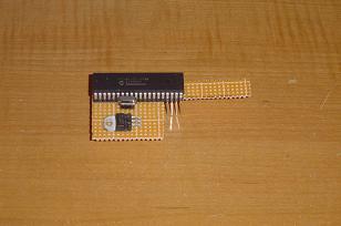
Step (8) - Notice The L Shaped Protoboard Leaves Room For A 9v»
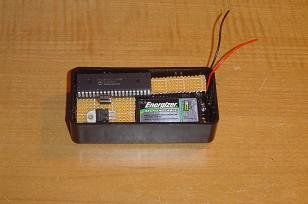
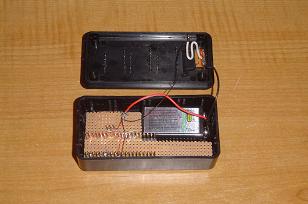
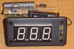
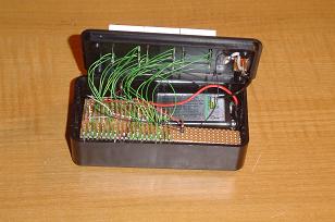
Step (9) - This Is How Things Should Go Inside The Enclosure»
Step (10) - Wire-up The Board According To The Schematic»
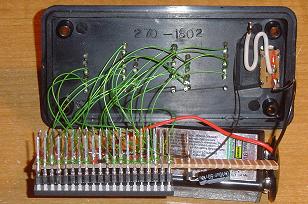
Step (11) - Front-View Of The Finished Wiring»
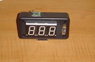
Step (12) - Drill Holes For The Accelerometer»
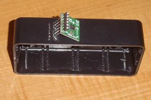
Step (13) - E-poxy The Accelerometer Onto The Enclosure»
Step (14) - Wirewrap The Accelerometer To The PIC»
Step (15) - Tape The Surrounding Edges With Electrical Tape»
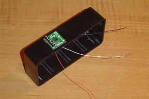
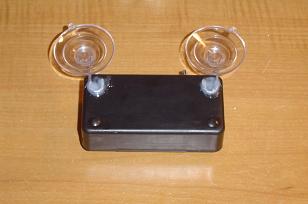
Step (16) - E-poxy The Two Suction Cups Onto The Back»
Now that we've seen the schematic and a little bit of the theory let's take a look at the step-by-step process for building your personal g-force meter.
Step (1) - Gather All The Parts Previously Mentioned»
Step (2) - Clear Out The Insides Of The Plastic Enclosure»
Step (3) - Map The Pinout Of The 7-Seg LEDs On a Piece Of Paper»
Step (4) - Drill Tiny Holes For Each Pin Of The 7-Seg LEDs»
Step (5) - E-poxy the LEDs Onto The Enclosure»
Step (6) - Drill A Hole For The On/Off Switch & E-poxy It In»
Step (7) - Cut Your Proto Board To Fit Into The Enclosure»
Step (8) - Notice The L Shaped Protoboard Leaves Room For A 9v»
Step (9) - This Is How Things Should Go Inside The Enclosure»
Step (10) - Wire-up The Board According To The Schematic»
Step (11) - Front-View Of The Finished Wiring»
Step (12) - Drill Holes For The Accelerometer»
Step (13) - E-poxy The Accelerometer Onto The Enclosure»
Step (14) - Wirewrap The Accelerometer To The PIC»
Step (15) - Tape The Surrounding Edges With Electrical Tape»
Step (16) - E-poxy The Two Suction Cups Onto The Back»