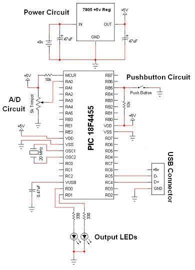
Schematic Overview
Hardware design for USB is actually quite minimal, which is a big plus for us. However, what you quickly find out with USB is that the easy hardware design means the communication and control software is very complex, we'll see more about that in the theory and software sections. The main devices used in the circuit are the PIC 18F4455, USB Connector and LM7805.
View Full Schematic
Schematic Specifics
Power Circuit
The +5v output from the power circuit comes from the LM7805 regulator. Notice the 47uF capacitors on the input and output. These are meant to be DC filtering capacitors, which smooth out the constant DC voltage being fed to the microcontroller from the 7805 regulator.
USB Connection and Output LEDs
Make sure you double check your USB pinout. A common mistake when wiring the PIC to the USB connector is getting the D+ and D- signals backwards. So if you're sure that the PIC is running your perfect code, but the USB device isn't coming up properly, switch D+ and D-, it might just magically fix your problem! The output LEDs will be simple 'toggle' LEDs. The program running on our laptop will be able to toggle them on and off with the push of a button.
A/D and Push Button Circuits
The A/D circuit is a standard 3 pin, Connected to Power, Signal Out and Ground circuit. The signal output goes into RA0 which is the Analog to Digital converter. After the PIC converts this signal it should send the data to the Laptop via USB. The laptop will the visually display the trimpot's value. The push button will do a similar thing, when the button is pushed, the laptop application should update with a notification that it has been pressed. These are simple ideas, but when done over USB they become rather complicated as we'll see in the theory section.
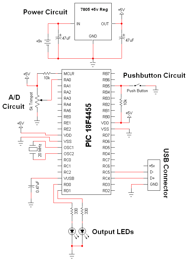