Hardware Design
When it comes to USB, the hardware design is as simple as it gets. A few wires and the external input/output parts are all that you need. However, this ease, is made up for by the complexity of the protocol seen in the theory section, and in the software.
Building The Circuit
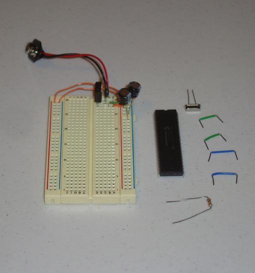
Here I have all the parts used in this project laid out for you to see. They were also listed in the parts section of this write-up.
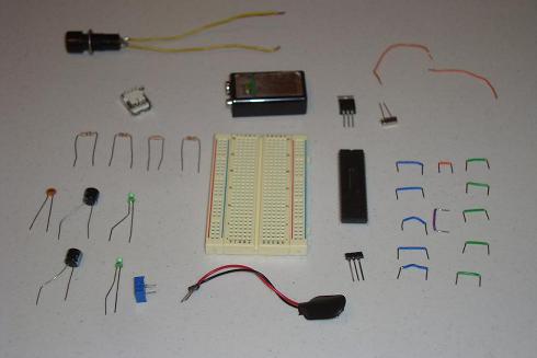
·Now, we start assembling the circuit, starting with the power supply, 7805.
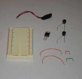
·The PIC circuit is up next, just connecting power, grounds and MCLR.
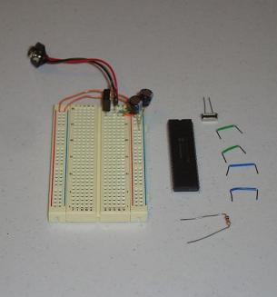
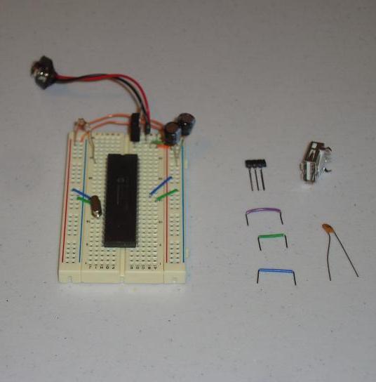
·The USB connector circuit is up next, connect it according to the schematic.
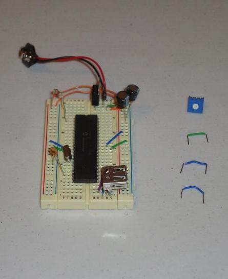
·The trimpot is connected next, to power, ground and to the PIC.
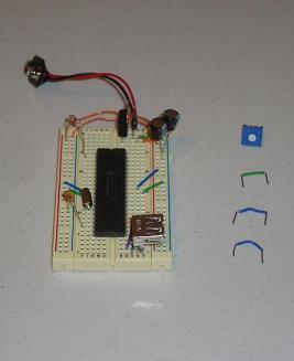
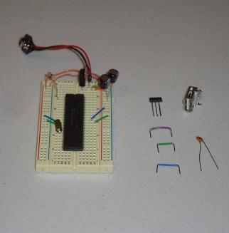
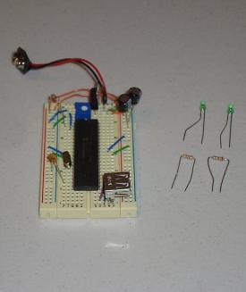
·LEDs connect to PORTD Pin 0 and Pin 1, I used current limiting resistors.
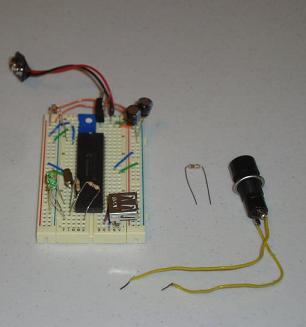
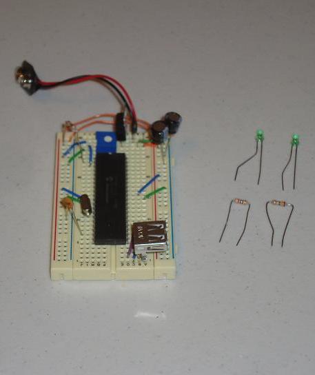
·The last connection is the push button and pull-up resistor.
·Now we can see the completed circuit!
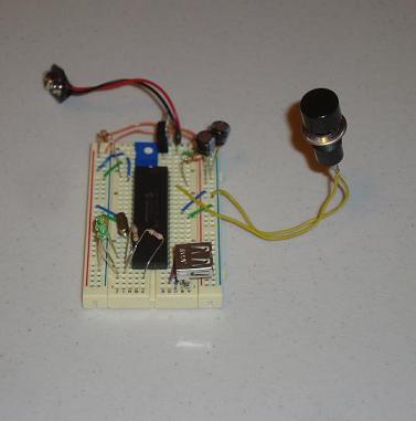
·With the hardware built, let's throw the software on it and test it out.
When it comes to USB, the hardware design is as simple as it gets. A few wires and the external input/output parts are all that you need. However, this ease, is made up for by the complexity of the protocol seen in the theory section, and in the software.
Building The Circuit
Here I have all the parts used in this project laid out for you to see. They were also listed in the parts section of this write-up.

·Now, we start assembling the circuit, starting with the power supply, 7805.

·The PIC circuit is up next, just connecting power, grounds and MCLR.
·The USB connector circuit is up next, connect it according to the schematic.
·The trimpot is connected next, to power, ground and to the PIC.
·LEDs connect to PORTD Pin 0 and Pin 1, I used current limiting resistors.
·The last connection is the push button and pull-up resistor.

·Now we can see the completed circuit!

·With the hardware built, let's throw the software on it and test it out.