Project Info
Author: Chris
Difficulty: Easy
Time Invested: 3 Hours
Prerequisites:
Take a look at the above
articles before continuing
to read this article.
Author: Chris
Difficulty: Easy
Time Invested: 3 Hours
Prerequisites:
Take a look at the above
articles before continuing
to read this article.
In this article, we shall look at how to build an RGB LED controller so that we have accurate and independant control over all three colors at any instant. The method of Fading LEDs via PWM will be leveraged for this design, since our goal here is quite similar, but with more control paths.
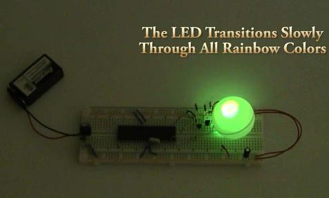
Purpose & Overview of this project
The purpose of this project is to build an RGB LED controller that can display all the colors of the rainbow is a slow, but methodical motion. A microcontroller should be used with 3 digital outputs. An interrupt timer routine will be used to keep track of elapsed time, along with counters to know what duty cycle the PWM control should be outputting.
The PIC 18F452 will be used as the microcontroller of this project with a 40 MHz crystal clock. Running this fast will allow the microcontroller a greater resolution of control for the PWM's duty cycle. A common-cathode high intensity RGB LED will be used with 3 2N2222 general purpose transistors to control switching when the R/G/B portions of the LED should be connected to power or ground.