Schematic Overview
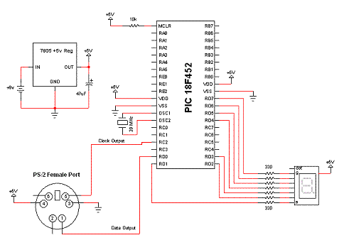
The schematic for this tutorial was kept as simple as possible so we could keep focus on where the PS/2 communication connects to the PIC. You can see the completed schematic for this project below. The main parts in the schematic are the 7805, 18F452 and PS/2 Port.

View Full Schematic
Schematic Specifics
Power Regulator
If you follow my projects and tutorials you'll recognize this circuit. It's an extremely simple and straight forward +5v regulator circuit with bypass capacitor.
PS/2 Connector
Be sure to look up the pinout for the PS/2 connector that you end up using, some might have different pinouts. Pins 2 and 6 are reserved for future use and are not used to communicate with the keyboard so they aren't wired up. Pins 4 and 3 are +5v and ground. Pins 1 and 5 are the Serial Data output and Clock output.
7 Segment LED Display
For whatever reason, I picked up a common anode 7 segment display (I'm used to using the common cathode ones). This means inside of the 7 segment display, each LED's anode is connected together to one pin, specifically the +5v input. Each of the other 7 pins to the PIC must provide a +0v potential to turn on the LED, or a logic 0. It's all a little backwards, don't stress over it too much.
The schematic for this tutorial was kept as simple as possible so we could keep focus on where the PS/2 communication connects to the PIC. You can see the completed schematic for this project below. The main parts in the schematic are the 7805, 18F452 and PS/2 Port.

View Full Schematic
Schematic Specifics
Power Regulator
If you follow my projects and tutorials you'll recognize this circuit. It's an extremely simple and straight forward +5v regulator circuit with bypass capacitor.
PS/2 Connector
Be sure to look up the pinout for the PS/2 connector that you end up using, some might have different pinouts. Pins 2 and 6 are reserved for future use and are not used to communicate with the keyboard so they aren't wired up. Pins 4 and 3 are +5v and ground. Pins 1 and 5 are the Serial Data output and Clock output.
7 Segment LED Display
For whatever reason, I picked up a common anode 7 segment display (I'm used to using the common cathode ones). This means inside of the 7 segment display, each LED's anode is connected together to one pin, specifically the +5v input. Each of the other 7 pins to the PIC must provide a +0v potential to turn on the LED, or a logic 0. It's all a little backwards, don't stress over it too much.