Hardware Design
Looking at the theory and proposed schematic is fun, but we need to actually build this thing and see it in action. Below are the steps that it takes to build the circuit on a breadboard.
Building The Circuit
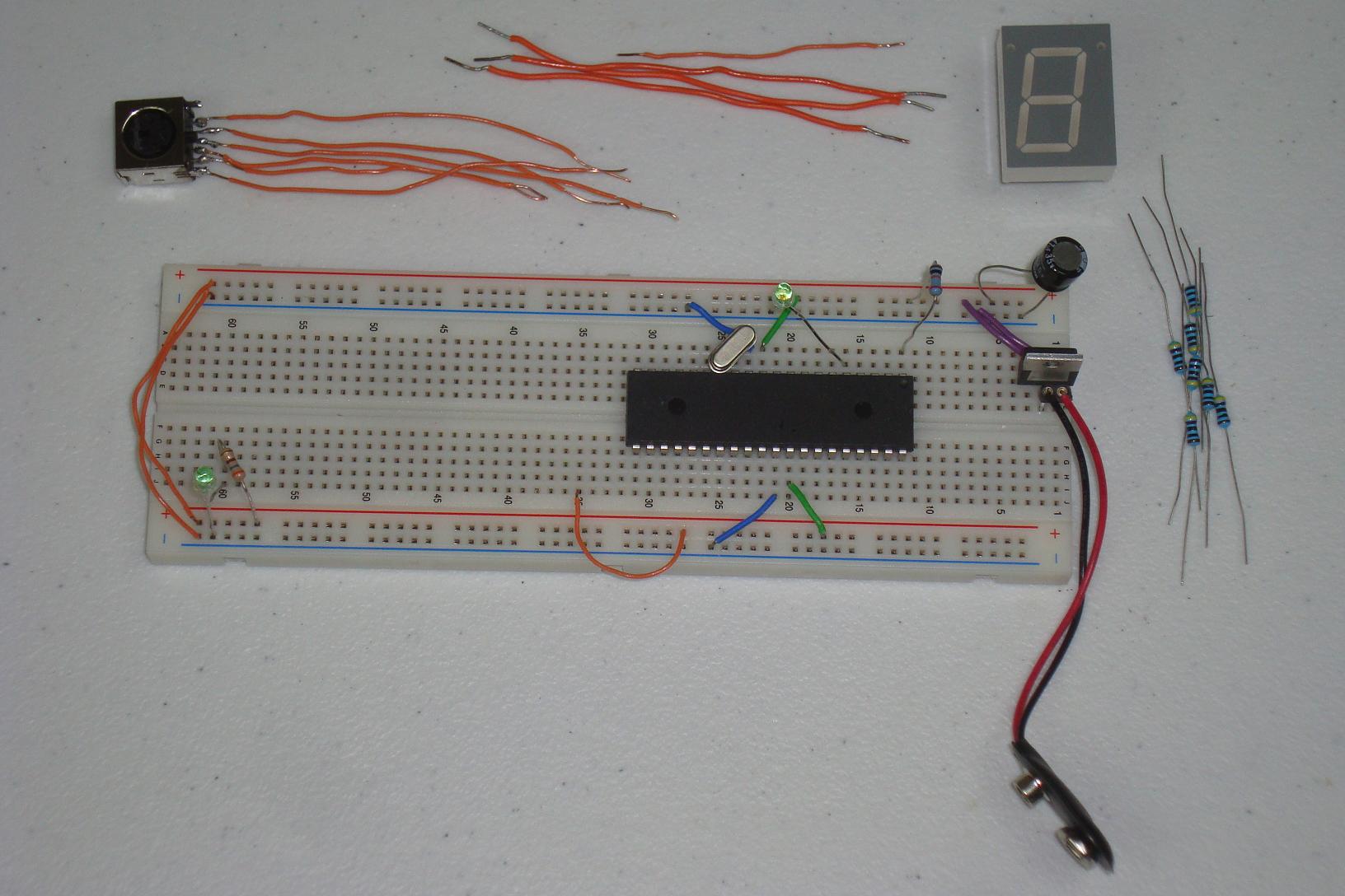
Get your parts together and follow the schematic. I built mine and in stages as you can see below...
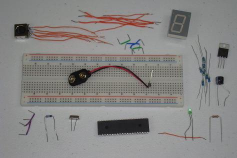
·First the power regulator circuit is connected on the breadboard.
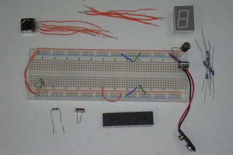
·The PIC microcontroller circuit comes next.
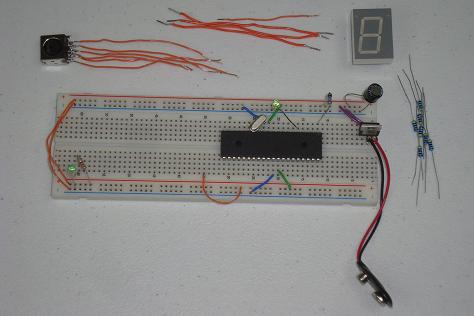
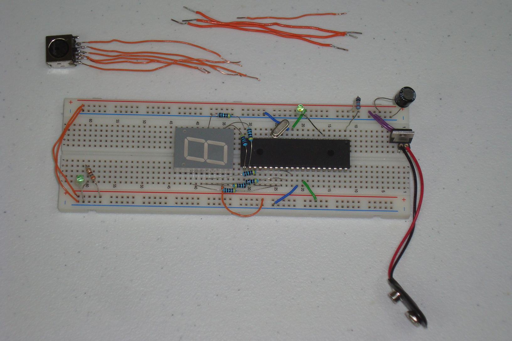
·I put the 7 Segment LED display here. The resistors connect it to the PIC.
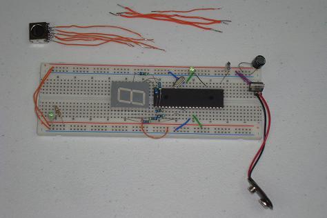
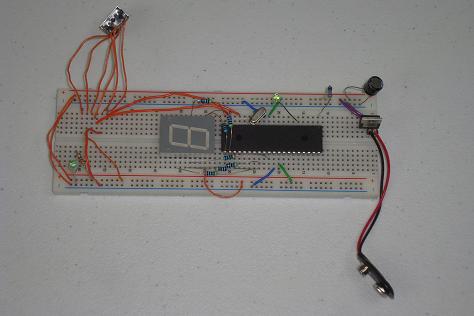
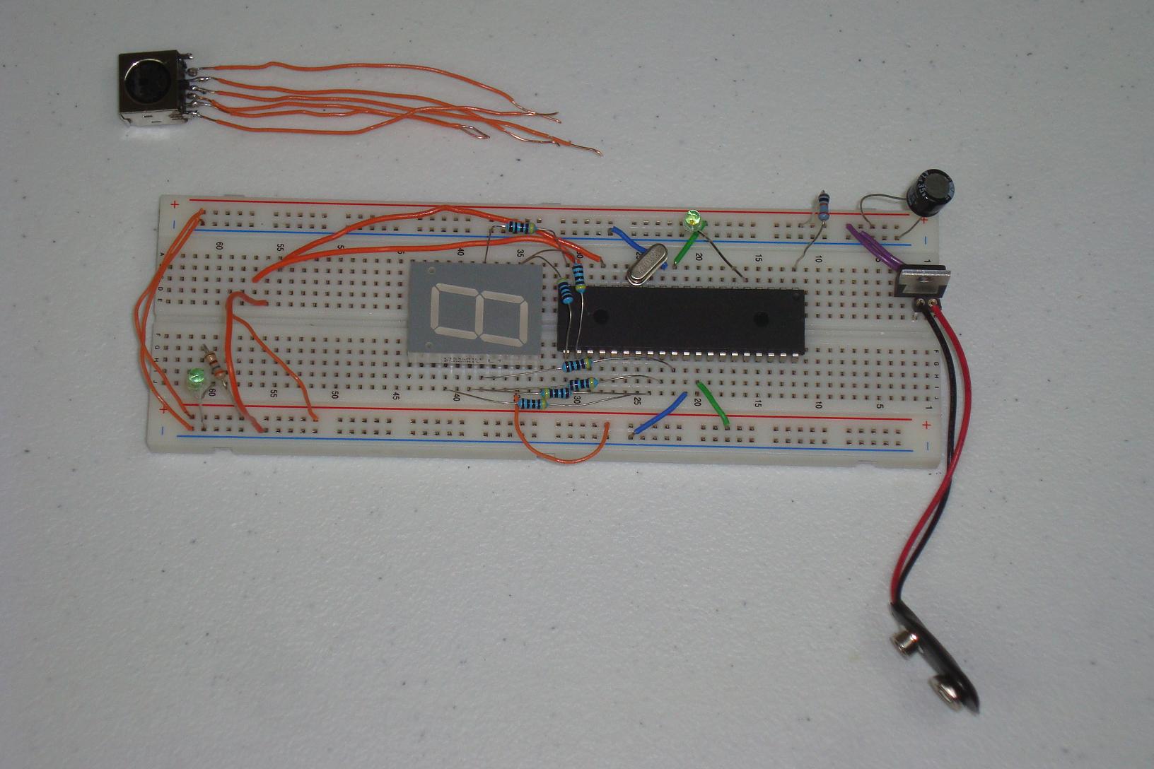
·Next, 4 wires carry power, ground, data and clk to the PS/2 female connector.
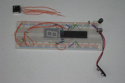
·The PS/2 female connector is connected to the breadboard with some lead wires I soldered to it.
·Presto, Finished! Just follow the schematic if you're in doubt. Look out! Your 7-Segment display might be wired differently than mine. Look up the datasheet and see which wires turn on which segment so you know what is going on!
Looking at the theory and proposed schematic is fun, but we need to actually build this thing and see it in action. Below are the steps that it takes to build the circuit on a breadboard.
Building The Circuit
Get your parts together and follow the schematic. I built mine and in stages as you can see below...

·First the power regulator circuit is connected on the breadboard.

·The PIC microcontroller circuit comes next.
·I put the 7 Segment LED display here. The resistors connect it to the PIC.
·Next, 4 wires carry power, ground, data and clk to the PS/2 female connector.
·The PS/2 female connector is connected to the breadboard with some lead wires I soldered to it.

·Presto, Finished! Just follow the schematic if you're in doubt. Look out! Your 7-Segment display might be wired differently than mine. Look up the datasheet and see which wires turn on which segment so you know what is going on!