Schematic Overview
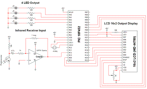
The Infrared IR Receiver circuit is not particularly unique. The main components are the phototransistor, the microcontroler and the amplifier. If you can understand how these three devices transfer data, then you should have no problem getting the circuit to work on your own.

View Full Schematic
Schematic Specifics
Infrared Receiver Input
This is where the true magic happens. The phototransistor receives the digitally encoded data from an IR emitting diode inside of the Direct TV Remote. The Op-Amp amplifies and inverts the signal which is finally passed to the microcontroller.
LCD 16x2 Circuit
This is the LCD used to output the current status of which button has been pressed. It's mainly here to verify that the controller is working. This 16x2 module works off of the HD 44780 parallel data standard. See the Interfacing LCD ⇒ PIC tutorial for more information on exactly how this device works.
4-LED Output
Similar to how the LCD is used, the LEDs are just there for verification purposes and to add some more functionality to the controller. The LEDs will switch on or off when you press one of the colored buttons on the remote control.
The Infrared IR Receiver circuit is not particularly unique. The main components are the phototransistor, the microcontroler and the amplifier. If you can understand how these three devices transfer data, then you should have no problem getting the circuit to work on your own.

View Full Schematic
Schematic Specifics
Infrared Receiver Input
This is where the true magic happens. The phototransistor receives the digitally encoded data from an IR emitting diode inside of the Direct TV Remote. The Op-Amp amplifies and inverts the signal which is finally passed to the microcontroller.
LCD 16x2 Circuit
This is the LCD used to output the current status of which button has been pressed. It's mainly here to verify that the controller is working. This 16x2 module works off of the HD 44780 parallel data standard. See the Interfacing LCD ⇒ PIC tutorial for more information on exactly how this device works.
4-LED Output
Similar to how the LCD is used, the LEDs are just there for verification purposes and to add some more functionality to the controller. The LEDs will switch on or off when you press one of the colored buttons on the remote control.