Hardware Design
When building this design be sure to follow the circuit diagram from the schematic section precisely or else things will turn out differently. Luckily, this tutorial only requires breadboarding a few parts together. I'm a bit of a cheater as I already have my LCD wire-wrapped to my PIC board from the previous tutorial (Build A Digital Tachometer/RPM Counter).
Building The Circuit
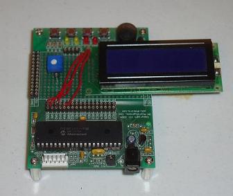
·First make sure the LCD gets connected to the appropriate PINs.
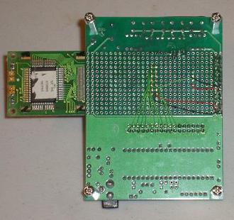
·Here's a bottom-view of the wire=wrap job I did to connect the PIC to the LCD
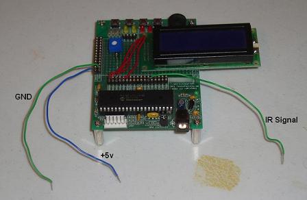
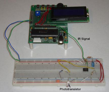
·The breadboard will need power and ground from the PIC board and the IR signal comes to the PIC board from the breadboard.
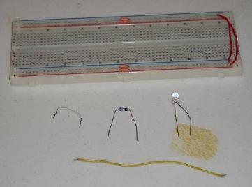
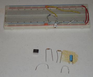
·First use these parts to build the simple IR receiver.
·Now add the rest of the amplifier circuit and connect the 3 wires from the PIC board.
·There you have it. How easy was that? Didn't even take an hour! Now let's program the PIC with the software to make everyone work.
When building this design be sure to follow the circuit diagram from the schematic section precisely or else things will turn out differently. Luckily, this tutorial only requires breadboarding a few parts together. I'm a bit of a cheater as I already have my LCD wire-wrapped to my PIC board from the previous tutorial (Build A Digital Tachometer/RPM Counter).
Building The Circuit
·First make sure the LCD gets connected to the appropriate PINs.
·Here's a bottom-view of the wire=wrap job I did to connect the PIC to the LCD
·The breadboard will need power and ground from the PIC board and the IR signal comes to the PIC board from the breadboard.
·First use these parts to build the simple IR receiver.
·Now add the rest of the amplifier circuit and connect the 3 wires from the PIC board.
·There you have it. How easy was that? Didn't even take an hour! Now let's program the PIC with the software to make everyone work.