Project Info
Author: Chris
Difficulty: Medium
Time Invested: 4 Hours
Prerequisites:
Take a look at the above
articles before continuing
to read this article.
Author: Chris
Difficulty: Medium
Time Invested: 4 Hours
Prerequisites:
Take a look at the above
articles before continuing
to read this article.
In this article we explore the flexibilty and capability of FPGAs and specifically CPLDs for creating an RS232 serial interface. Our main goal will be to send ASCII codes from a PC to our CPLD Dev Board and display them on a 7 segment LED for verification.
Purpose & Overview of this project
The goal of this project is to create a system that can receive RS232 commands from a host computer. These commands will be translated and displayed in a known format to verify that our communication channel indeed works. For this project, we'll verify accuracy using a 7 segment LED to display the decoded ASCII of numbers and letters. Simply put, if I press 'A' on the keyboard, the 7 segment led display will show an 'A'.
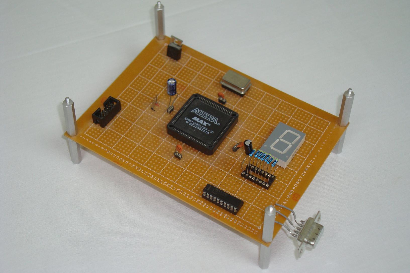
We will reach this goal by securing that our 7 segment LED output display still works, adding a 25.175 MHz clock signal input and adding a MAX233A to the board to translate RS232 signals to +5v digital logic signals.