Interrupt Theory
Now that we know what type of interrupt will be used on the PIC, we need to set it up properly by setting certain values in four important registers. Two will enable the interrupt and the other two configure the type of interrupt and priority levels we will be using.
PIC External Interrupt Registers

To setup the PIC to use interrupts, first we have to enable the interrupt that we want to use. In the PIC 18F452 datasheet the interrupt-on-change enable bit is located in the INTCON register, bit 4. It has the short name INT0IE. We will set this to 1 to enable it. Also, all interrupts need to be enabled, so bit 7, GIEH will also be enabled with a 1. This sets up the RB0, interrupt-on-change functionality. Lastly, bit 6 - GIEL is also enabled so that priority interrupt levels (high and low) can be used.

The INTCON3 register needs to have two bits set properly. The interrupt-on-change automatically assigns a high priority to INT0, so we will assign a low priority to the INT1 (RB1) interrupt-on-change. This way, we will have setup a high and a low priority interrupt. Bit 3 is the enabled bit for INT1. This will need to be set to 1 so that INT1 is enabled and can be used.
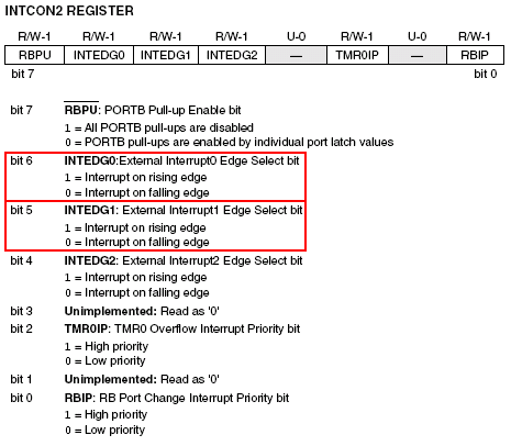
The second part of setting up the interrupt-on-change register for RB0/RB1 is to set whether the state change is a falling edge or rising edge change. The INTCON2 register is where we set this. We will set bit 6 and 5 to a '0', since we are designing for a falling edge interrupt. All of this information is located in the PIC 18F452 datasheet, so if you don't have it already, google search for it and download your own copy.
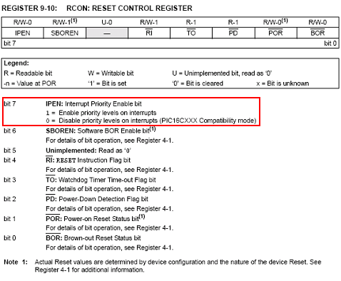
The very last register we need to set is the RCON register. Bit 7 enables priority interrupt levels on the PIC and so it should be set to 1. After we've set this last register, interrupts are enabled and ready to start interrupting the main program loop!
Now that we know what type of interrupt will be used on the PIC, we need to set it up properly by setting certain values in four important registers. Two will enable the interrupt and the other two configure the type of interrupt and priority levels we will be using.
To setup the PIC to use interrupts, first we have to enable the interrupt that we want to use. In the PIC 18F452 datasheet the interrupt-on-change enable bit is located in the INTCON register, bit 4. It has the short name INT0IE. We will set this to 1 to enable it. Also, all interrupts need to be enabled, so bit 7, GIEH will also be enabled with a 1. This sets up the RB0, interrupt-on-change functionality. Lastly, bit 6 - GIEL is also enabled so that priority interrupt levels (high and low) can be used.
The INTCON3 register needs to have two bits set properly. The interrupt-on-change automatically assigns a high priority to INT0, so we will assign a low priority to the INT1 (RB1) interrupt-on-change. This way, we will have setup a high and a low priority interrupt. Bit 3 is the enabled bit for INT1. This will need to be set to 1 so that INT1 is enabled and can be used.
The second part of setting up the interrupt-on-change register for RB0/RB1 is to set whether the state change is a falling edge or rising edge change. The INTCON2 register is where we set this. We will set bit 6 and 5 to a '0', since we are designing for a falling edge interrupt. All of this information is located in the PIC 18F452 datasheet, so if you don't have it already, google search for it and download your own copy.
The very last register we need to set is the RCON register. Bit 7 enables priority interrupt levels on the PIC and so it should be set to 1. After we've set this last register, interrupts are enabled and ready to start interrupting the main program loop!