Schematic Overview
From the basic CPLD Dev Board we will made two new additions. First a resistor network of 330Ω will be added and pulled up to +5v. Second, the 10 LED bar will be added, connected to the resistor network and also connected to the FPGA.
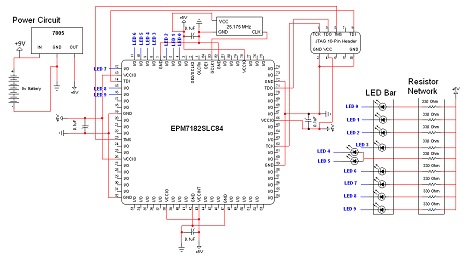
View Full Schematic
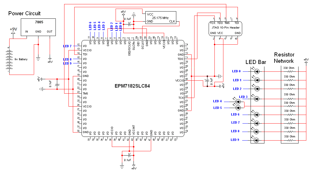
Schematic Specifics
Resistor Network
The resistor network is a series of 9 resistors that all connect to the same +5v power. Since we have 10 LEDs and only 9 resistors, the two middle LEDs will connect to the same resistor.
10 LED Bar
There's nothing too special about an LED bar, it's 10 LEDs in a row all with a cathode and an anode pin. However, the way that we're connecting the LEDs to the CPLD might seem backwards as when the CPLD outputs a logic '0', the LED will turn on and when the CPLD outputs a logic '1' the LED will turn off. This is because the cathode is connecting to the CPLD.
From the basic CPLD Dev Board we will made two new additions. First a resistor network of 330Ω will be added and pulled up to +5v. Second, the 10 LED bar will be added, connected to the resistor network and also connected to the FPGA.
View Full Schematic
Schematic Specifics
Resistor Network
The resistor network is a series of 9 resistors that all connect to the same +5v power. Since we have 10 LEDs and only 9 resistors, the two middle LEDs will connect to the same resistor.
10 LED Bar
There's nothing too special about an LED bar, it's 10 LEDs in a row all with a cathode and an anode pin. However, the way that we're connecting the LEDs to the CPLD might seem backwards as when the CPLD outputs a logic '0', the LED will turn on and when the CPLD outputs a logic '1' the LED will turn off. This is because the cathode is connecting to the CPLD.