The schematic seen earlier is only for the electrical portion of this project. The hardware portion of this project means cutting out some MDF pieces and drilling a bunch of holes in them for nuts and bolts to fit into.
The Layout
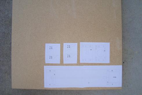
Before I started cutting, drilled or building I drew all the parts out in CorelDraw. I zipped the files and you can download them above if you'd like to. The reason for drawing things out like this, is because you can print and cut out the pieces, then glue them to your piece of MDF and cut along that piece of paper. I find it works a lot better than drawing the pieces on your wood with a pen and ruler.
Additional Parts List
Some miscellanous nuts and bolts are necessary for building the stage and mounting the motor to the setup. Below I listed these additional parts. You might need more or less depending on what you try to build.
Bolts
· 8 - 0.25" Diameter x 1" Length
· 4 - 0.25" Diameter x 1.25" Length
· 4 - 12-24 Diameter x 1.25" Length
· 1 - 18" Threaded Rod 0.25" Diameter
Nuts
· Coupling Nut - 0.25" Diameter
· 8 Nuts - 0.25" Diameter
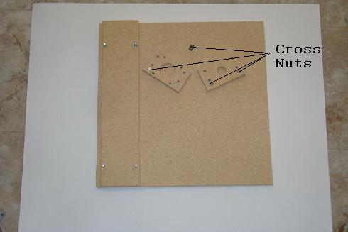
· 4 - Cross Nut(7mm OD x 12mm depth x 0.25” bore)
· 1 - Motor 1/4" Diameter Shaft Coupler
Cut Out The Pieces
·The pieces are pasted onto the wood and prepared for cutting.
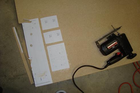
·Cut out the pieces with a saw. Here I used a jigsaw.
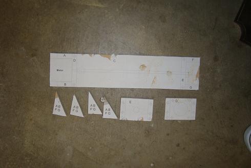
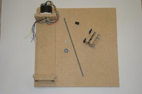
·The final pieces. The triangle pieces were meant for support, but aren't included in the final design.
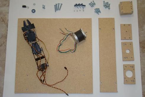
·These are all the pieces for the hardware portion of the project as listed above.

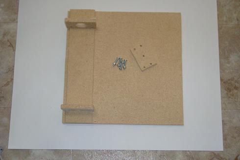
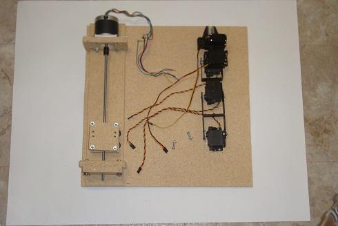
·First connect the large base and the motor-way using 1\4" bolts.
·Now bolt in the motor mount and the bearing mount.
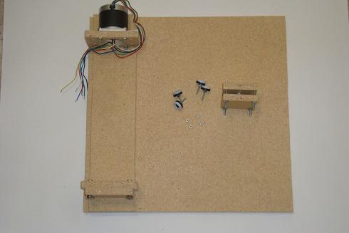
·One additional bearing mount board is added for stability.
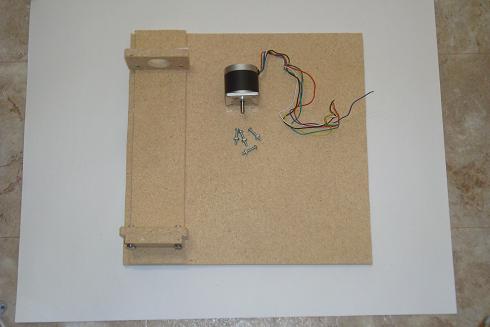
·Now mount the motor to the motor mount using the bolts.
·Build a small stage with leftover MDF wood. Add some small 'moving pads' to the bottom of the stage.
·Thread the rod through the stage and connect it to the motor shaft coupling and align the bearing so that it rests agains the nut and the wood. The threaded rod should spin freely.
·Now build up the servo arm and connect the base to the stage with 2 bolts.
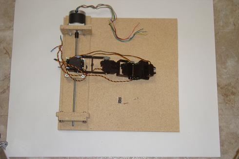
·Add the SPDT switch by screwing in two screws to mount it down.

·A closer look at the SPDT switch, used as a limit switch.
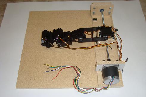
·The stage, mounts and arm is all finished and ready to go.
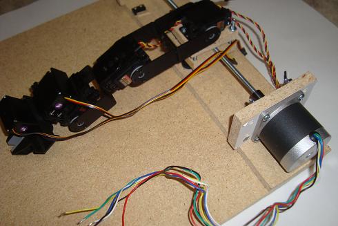
·A quick side-shot of the arm and the stepper motor.
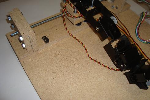
·The limit switch and the fully built robotic arm.