Schematic Overview
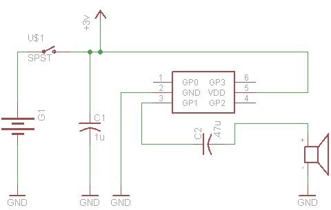
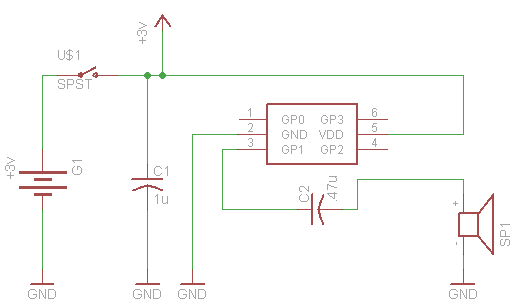
The schematic shown below is just as simple as it seems to be. This project is based upon the premise of using as little parts as possible to be as annoying as possible :) so its kept super duper simple!
View Full Schematic
Schematic Specifics
PIC10F202
The main processor for this board is the PIC10F202 which is a tiny microcontroller in a SOT-23 package with 6 pins (it's not labeled on the schematic--doh!, but I think its obvious which 6 pin part we're talking about). Although we're only actually using 3 of the pins: power, ground and output to the speaker.
Capacitors
Two capacitors are used in this design. The first capacitors is across the power and ground connections to make sure the PIC has enough current to operate nominally. The second capacitors appears before the speaker. This will increase the volume of the speaker a little bit.
Speaker
The speaker that we'll use is a generic ear-bud style speaker that we've cut off of a set of headphones. The PIC can't output too much current so don't expect it to drive an 8Ω speaker and be really loud, use some small ear-bud speakers like we did.
PCB Artwork
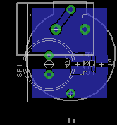
The PCB layout for this project is really simple. Most of the copper is used for a ground plane and a power plane. The smaller spots are all pads for the capacitors, battery, microcontroller and speaker.
View Board Layout
Pads vs. Thru-Holes
When you print it out you won't be able to tell the difference however. In the board layout tool (seen in the picture above) the green circles represent where the thru-hole parts will go and the surface mount parts are just square red pars, part of the rest of the copper on the board.
The schematic shown below is just as simple as it seems to be. This project is based upon the premise of using as little parts as possible to be as annoying as possible :) so its kept super duper simple!
View Full Schematic
Schematic Specifics
PIC10F202
The main processor for this board is the PIC10F202 which is a tiny microcontroller in a SOT-23 package with 6 pins (it's not labeled on the schematic--doh!, but I think its obvious which 6 pin part we're talking about). Although we're only actually using 3 of the pins: power, ground and output to the speaker.
Capacitors
Two capacitors are used in this design. The first capacitors is across the power and ground connections to make sure the PIC has enough current to operate nominally. The second capacitors appears before the speaker. This will increase the volume of the speaker a little bit.
Speaker
The speaker that we'll use is a generic ear-bud style speaker that we've cut off of a set of headphones. The PIC can't output too much current so don't expect it to drive an 8Ω speaker and be really loud, use some small ear-bud speakers like we did.
PCB Artwork
The PCB layout for this project is really simple. Most of the copper is used for a ground plane and a power plane. The smaller spots are all pads for the capacitors, battery, microcontroller and speaker.
View Board Layout
Pads vs. Thru-Holes
When you print it out you won't be able to tell the difference however. In the board layout tool (seen in the picture above) the green circles represent where the thru-hole parts will go and the surface mount parts are just square red pars, part of the rest of the copper on the board.