We saw the design of the PCB and the schematic, so its time to print out the artwork for it and get ironing. We'll use the toner-transfer process to create the actual PCB using the artwork in the PDF files to the right. You can also download the eagle project in the zip file to the right.
Building And Assembling The Annoy PCB
Since we're using the toner-transfer process to get the PCB artwork onto both sides of the board here's a quick advisory: if you're using ferric chloride as an etchant, wear gloves, goggles and safety gear. That stuff isn't very friendly to biological life.
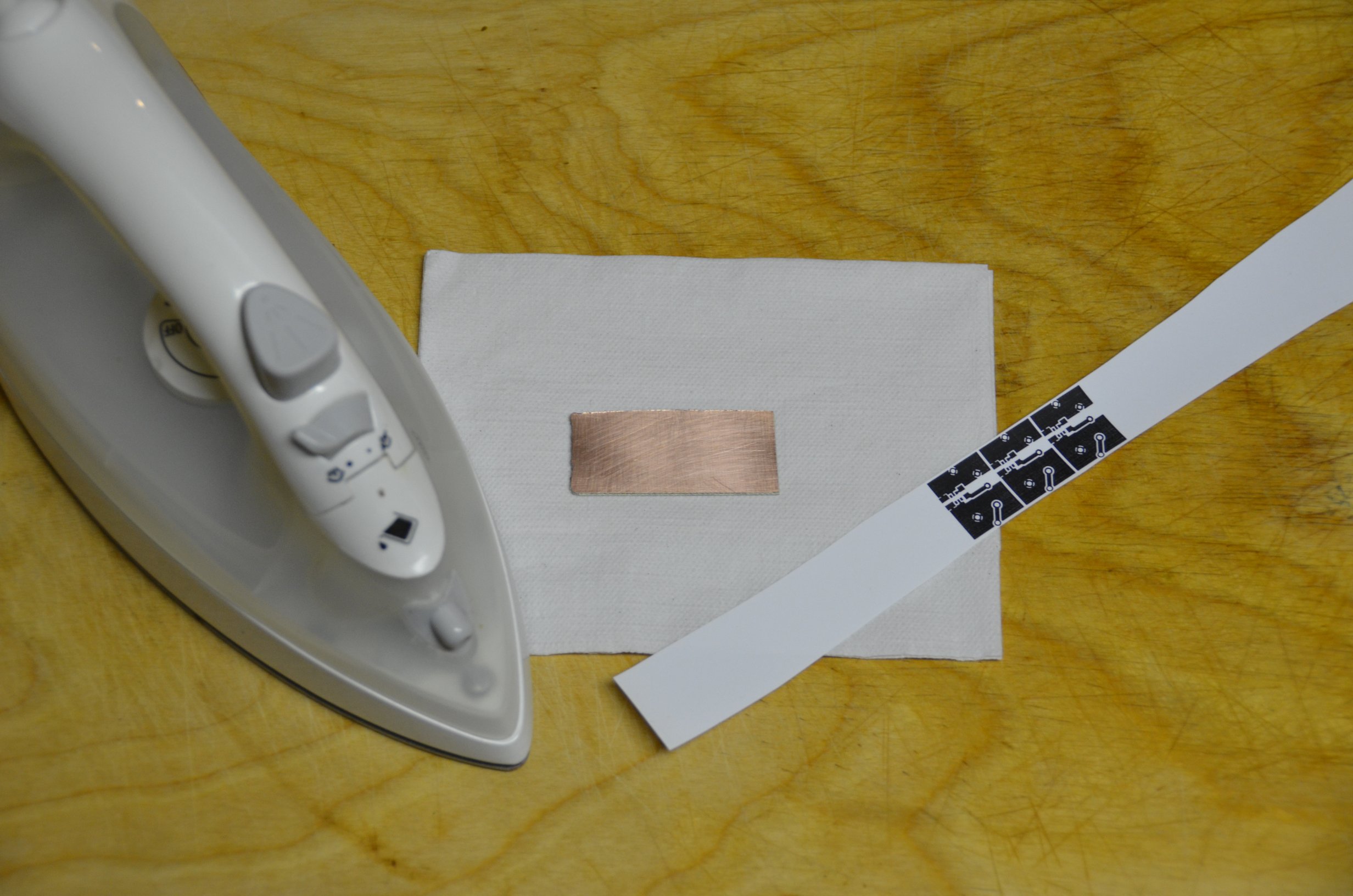
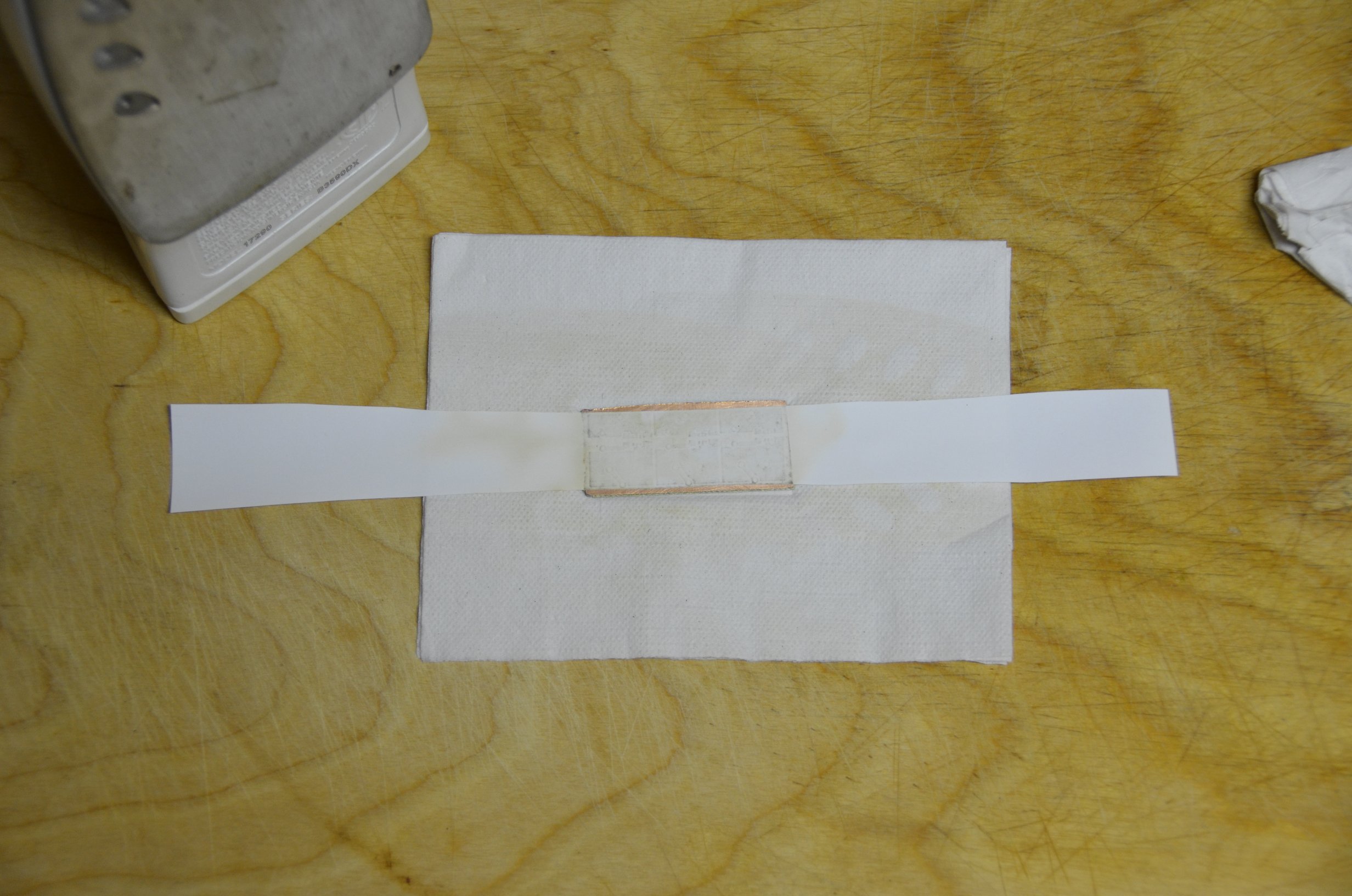
·Using an Iron, the toner is transferred to side A.
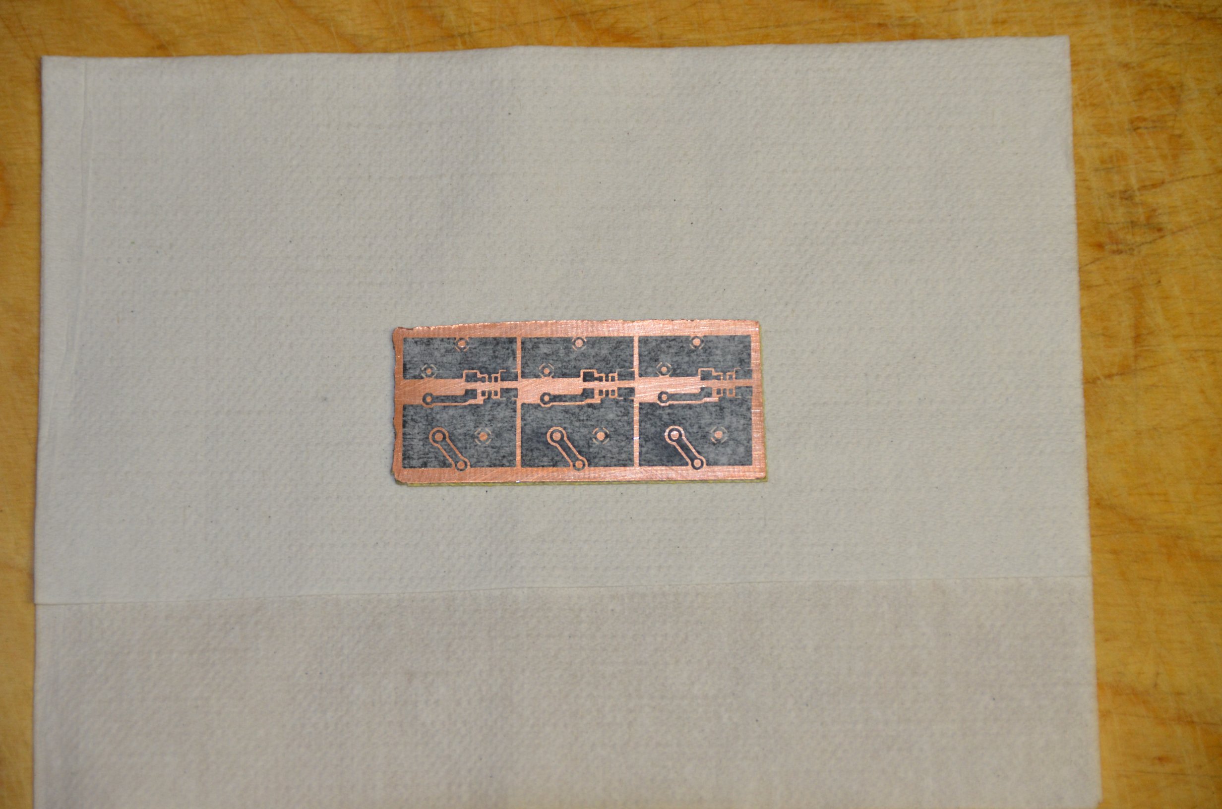
·When you pull off the paper and scrube the board a little the toner remains.
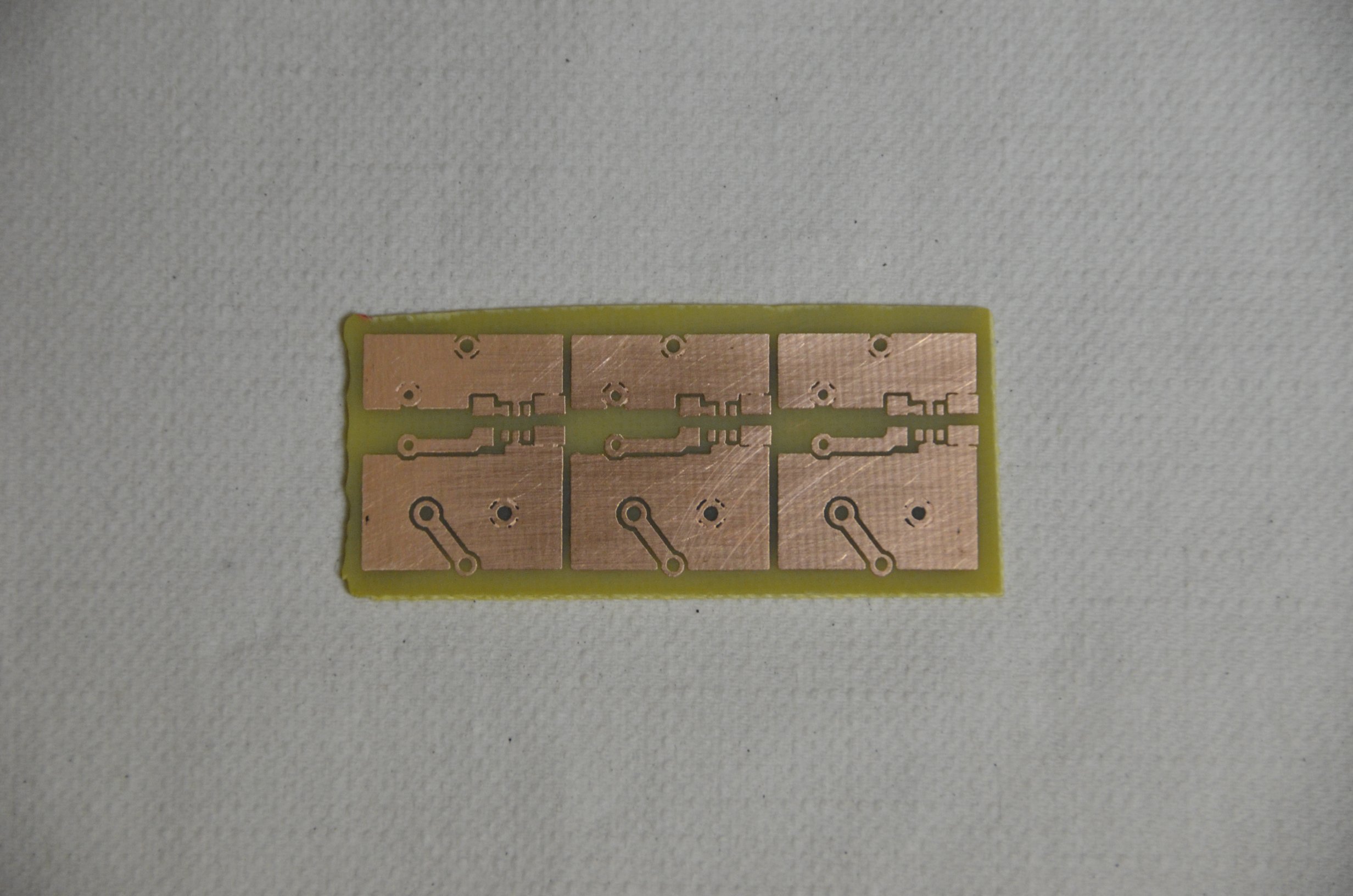
·Throw the board into a bucket of etchant and see how it comes out. You can see below, it came out looking quite nice.
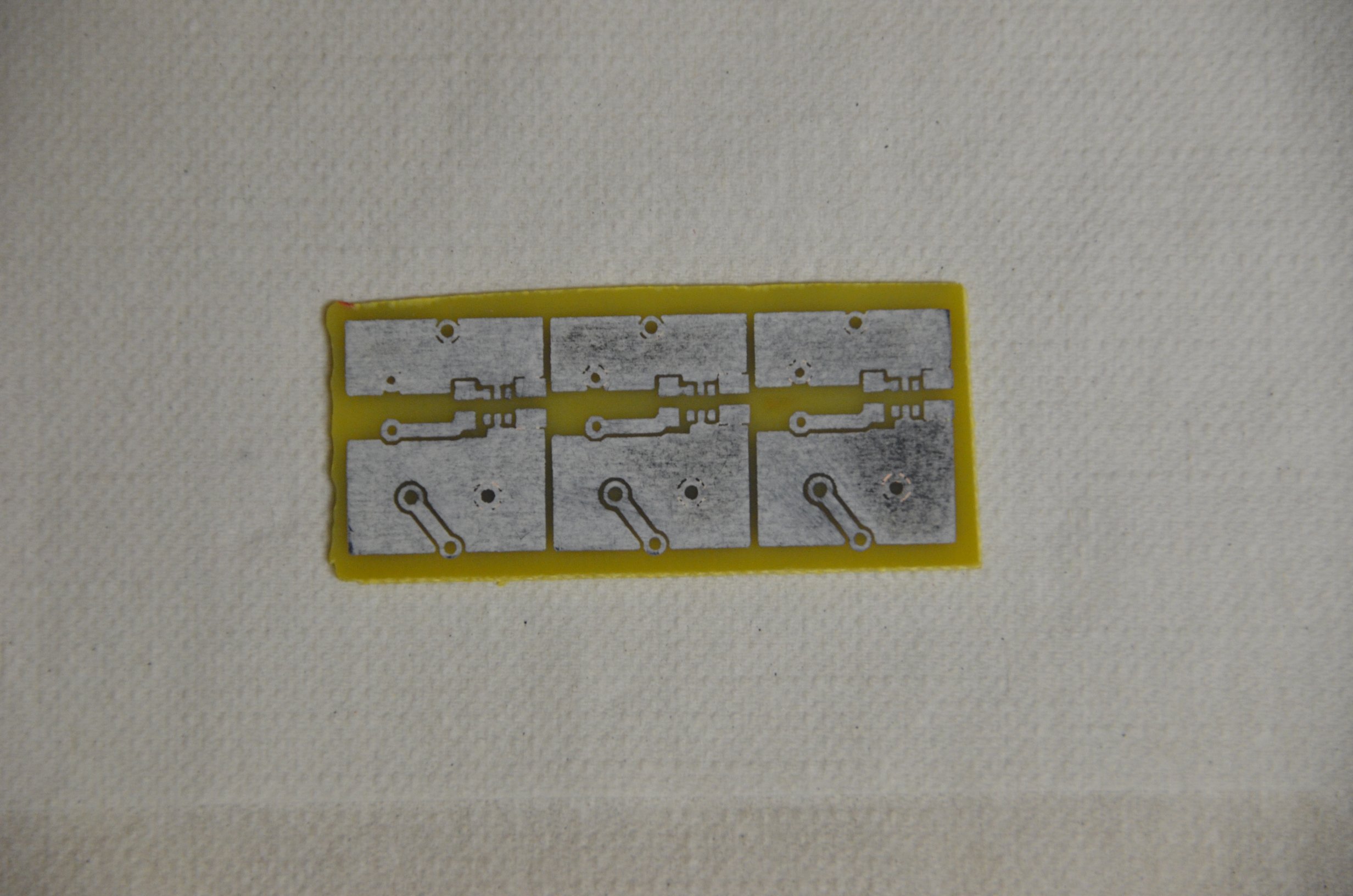
·After cleaning off the toner, the copper is exposed.
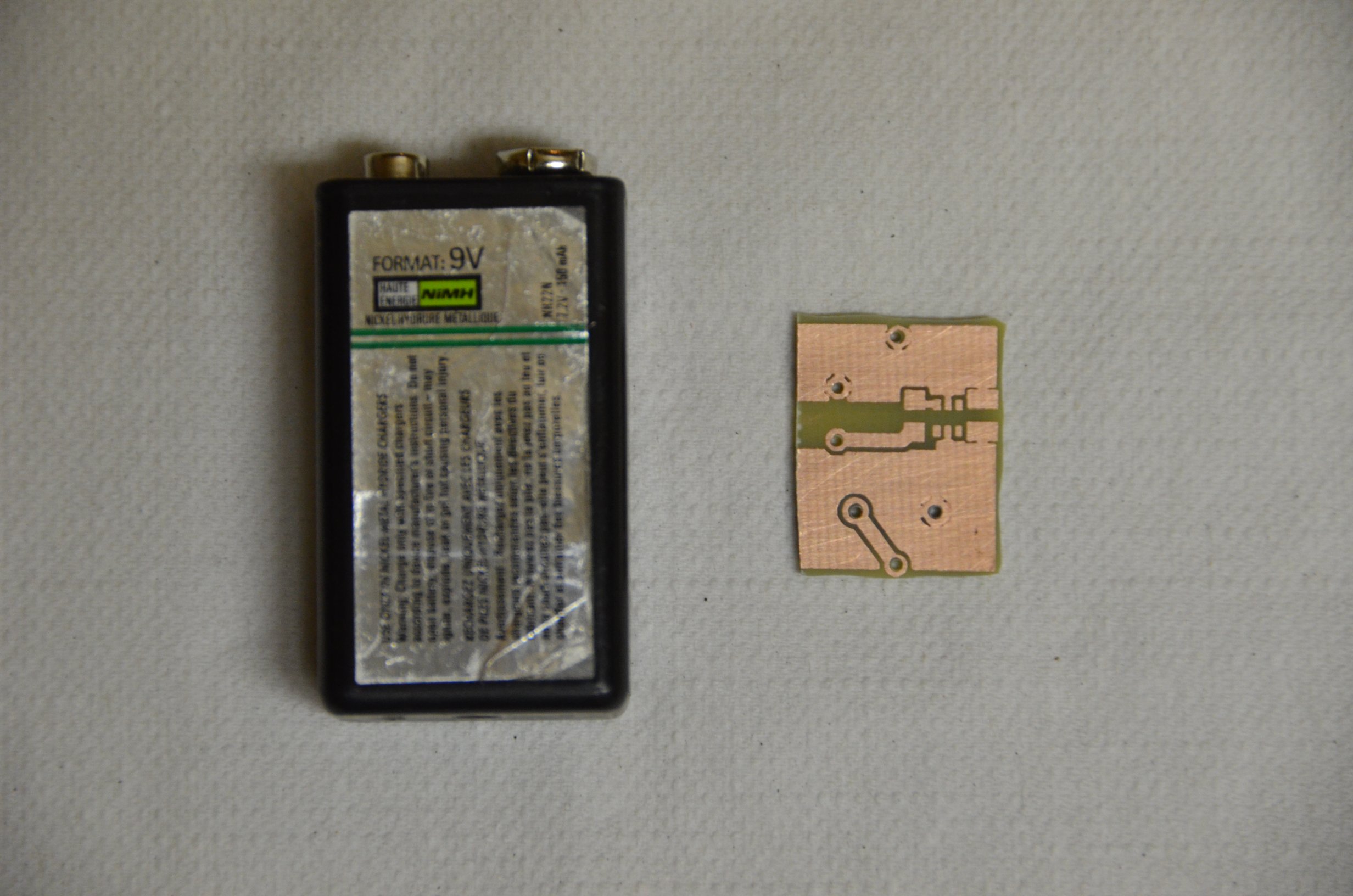
·Cut off one of the modules and drill the holes in it. +9v battery for size comparison.
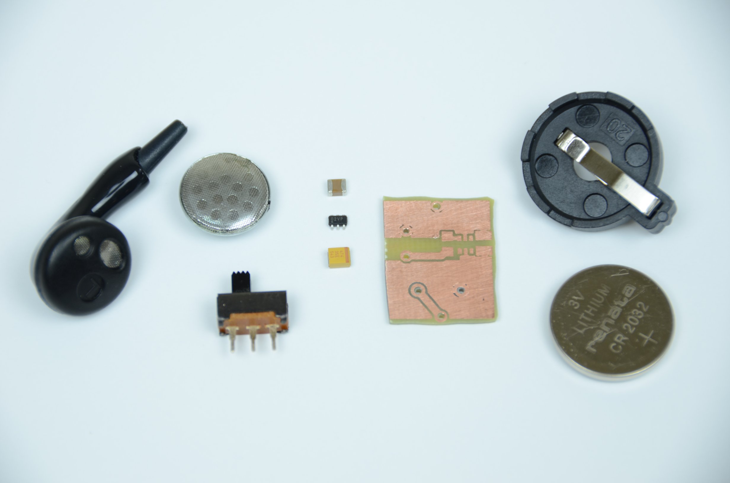
·Here are all the parts for the project.
·First I soldered (poorly) the two capacitors and the microcontroller to the board.
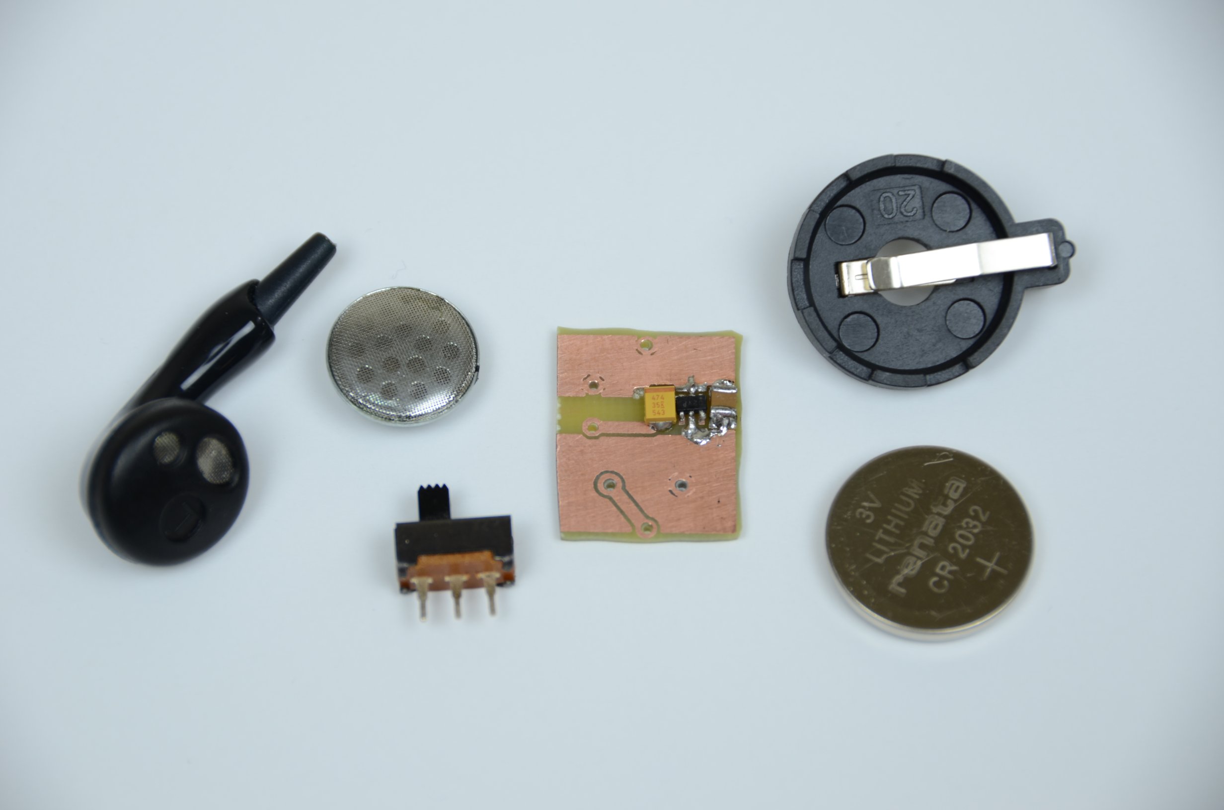
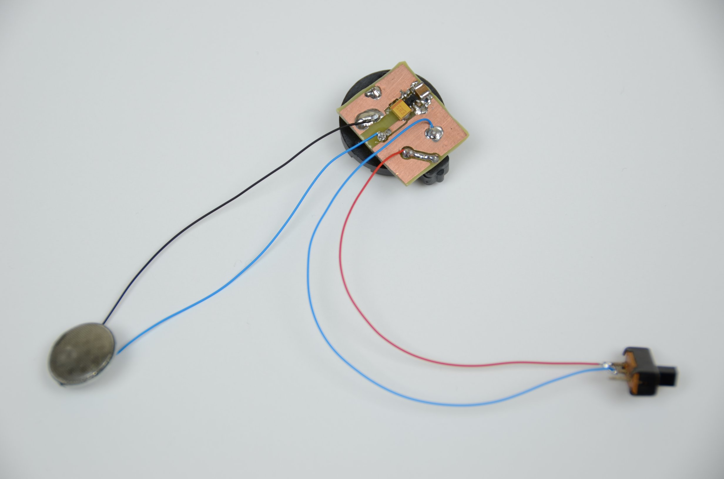
·Next. Solder in the battery holder and using some wire-wrap connect the push-button and speaker to the board.
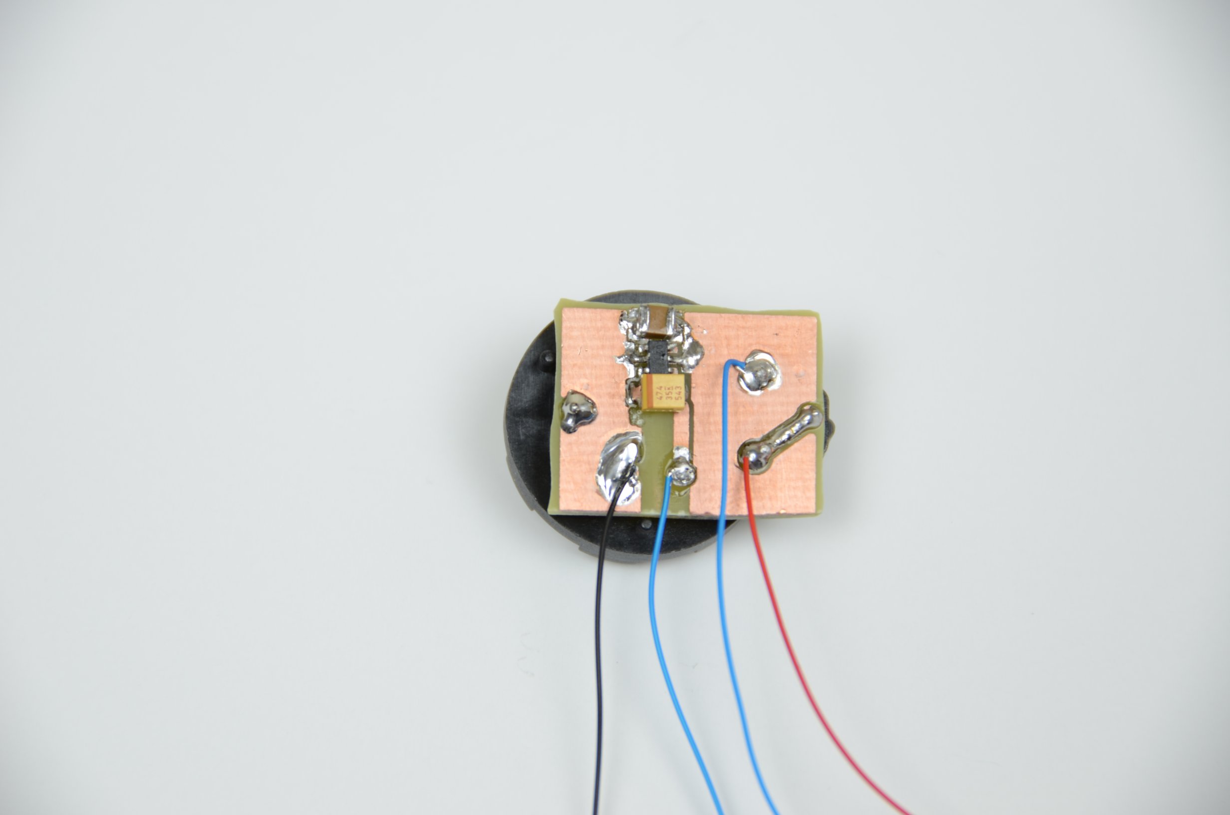
·When it's complete, here what you should have:
·Now let's take a look at the software side of this project.