Schematic Overview
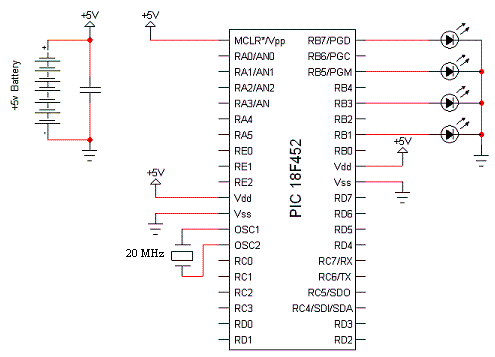
The schematic for this tutorial is very simple to wire up and put together. Very few parts are necessary and similarly very few wires are needed. Here is the full schematic for this tutorial:

View Full Schematic
Schematic Specifics
Power Circuit
The input voltage to the PIC is +5v. This will come from a battery. You could alternatively use a power adapter, so long as output voltage is +5v.
Main PIC Circuit
There is really nothing special happening here. Power (+5v) and Ground are all wired respectively. The MCLR/Vdd pin will always be tied high so that the PIC never resets.
LED Connections
Four LEDs will be connected & seperated on PORTB. PORTB7, 5, 3 & 1 will be wired to LEDs. The spacing is so that it will be easier to spot the different LEDs on the breadboard.
The schematic for this tutorial is very simple to wire up and put together. Very few parts are necessary and similarly very few wires are needed. Here is the full schematic for this tutorial:

View Full Schematic
Schematic Specifics
Power Circuit
The input voltage to the PIC is +5v. This will come from a battery. You could alternatively use a power adapter, so long as output voltage is +5v.
Main PIC Circuit
There is really nothing special happening here. Power (+5v) and Ground are all wired respectively. The MCLR/Vdd pin will always be tied high so that the PIC never resets.
LED Connections
Four LEDs will be connected & seperated on PORTB. PORTB7, 5, 3 & 1 will be wired to LEDs. The spacing is so that it will be easier to spot the different LEDs on the breadboard.