The H-Bridge
The original concept of the H-Bridge was being able to control the direction a motor was going. Forward or backward. This was achieved by managing current flow through circuit elements called transistors. The formation looks like an H and that's where it gets the name H-Bridge. Here is what it looks like:
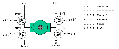
The picture above illustrates the 4 base cases that we can get out of the simple version of an H-Bridge. The two cases that interest us are when A & D are both 1 and when B & C are both 1.
When A & D are 1 current from the battery will flow from point A through the motor to D's ground. However for the case when B & C are both 1, current will flow in the opposite direction from B through the motor to C's ground.
LMD18245
To the right you'll see a sample of what the H-Bridge we'll be working with looks like with each pin labeled. For a complete description of what each pin does check out the datasheet at national.com.
For now we'll take a look at a unique feature that the LMD182xx series of H-Bridges offers us. It is called 'current sensing'. This is part of what the CS pin has to offer us.
H-Bridge Current Sensing
This feature allows us to limit the maximum amount of current that the motors can use. The stepper motor we are using for this tutorial is rated at 250mA. This means the maximum current it will ever sink is 250mA.
 Using this formula we can now define the max current. In the above example we see
a max current of 275.74mA is allowed. Rg is the component that we can change to achieve that max current value. Our stepper motor wants 250mA to run so this will be
more than enough.
Using this formula we can now define the max current. In the above example we see
a max current of 275.74mA is allowed. Rg is the component that we can change to achieve that max current value. Our stepper motor wants 250mA to run so this will be
more than enough.
Varying Stepper Motor Speed
In DC Motors varying the the M4-M1 inputs gave us different speeds because it varied the current flow allowed to the motor. This won't work with stepper motors. We'll need to instead decide how often we want to step. This means that we slow down the stepper motor by delaying between steps. The length of that delay will decide overall speed. We'll see this in the code.
The original concept of the H-Bridge was being able to control the direction a motor was going. Forward or backward. This was achieved by managing current flow through circuit elements called transistors. The formation looks like an H and that's where it gets the name H-Bridge. Here is what it looks like:
The picture above illustrates the 4 base cases that we can get out of the simple version of an H-Bridge. The two cases that interest us are when A & D are both 1 and when B & C are both 1.
When A & D are 1 current from the battery will flow from point A through the motor to D's ground. However for the case when B & C are both 1, current will flow in the opposite direction from B through the motor to C's ground.
LMD18245 Pinout
To the right you'll see a sample of what the H-Bridge we'll be working with looks like with each pin labeled. For a complete description of what each pin does check out the datasheet at national.com.
For now we'll take a look at a unique feature that the LMD182xx series of H-Bridges offers us. It is called 'current sensing'. This is part of what the CS pin has to offer us.
H-Bridge Current Sensing
This feature allows us to limit the maximum amount of current that the motors can use. The stepper motor we are using for this tutorial is rated at 250mA. This means the maximum current it will ever sink is 250mA.
Using this formula we can now define the max current. In the above example we see
a max current of 275.74mA is allowed. Rg is the component that we can change to achieve that max current value. Our stepper motor wants 250mA to run so this will be
more than enough.Varying Stepper Motor Speed
In DC Motors varying the the M4-M1 inputs gave us different speeds because it varied the current flow allowed to the motor. This won't work with stepper motors. We'll need to instead decide how often we want to step. This means that we slow down the stepper motor by delaying between steps. The length of that delay will decide overall speed. We'll see this in the code.