Hardware Design
Now the fun part begins, we get to actually build the project. All the steps seen below follow the schematic and I added a power LED to know when the power is connected.
Building The Circuit
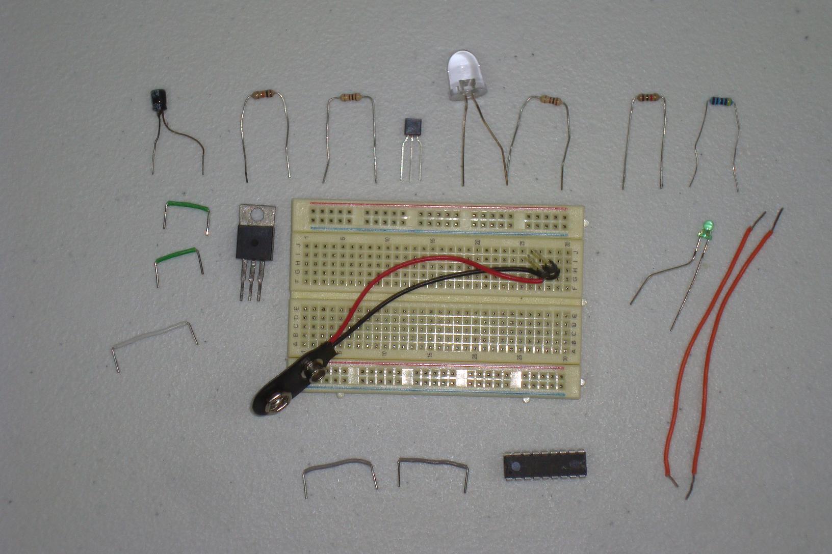
Get your parts together and follow the schematic. I assembled the circuit in stages as you can see below...

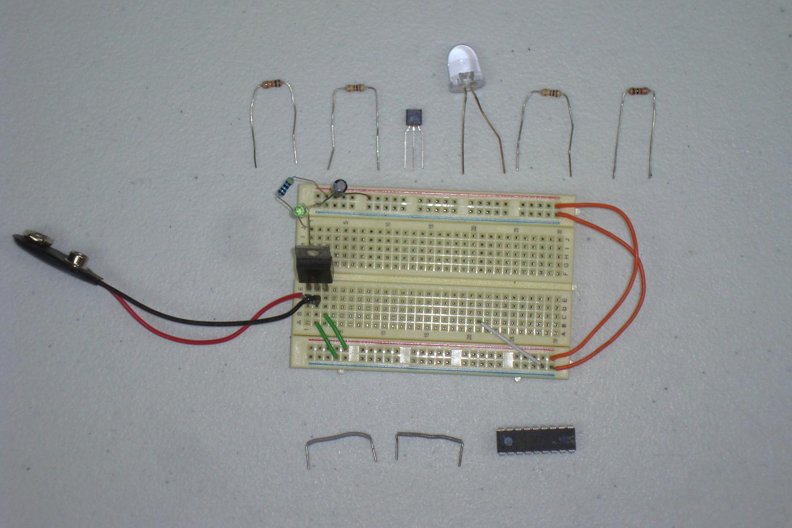
·First the power regulator circuit is connected.
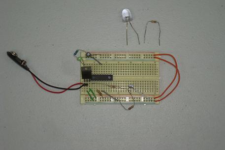
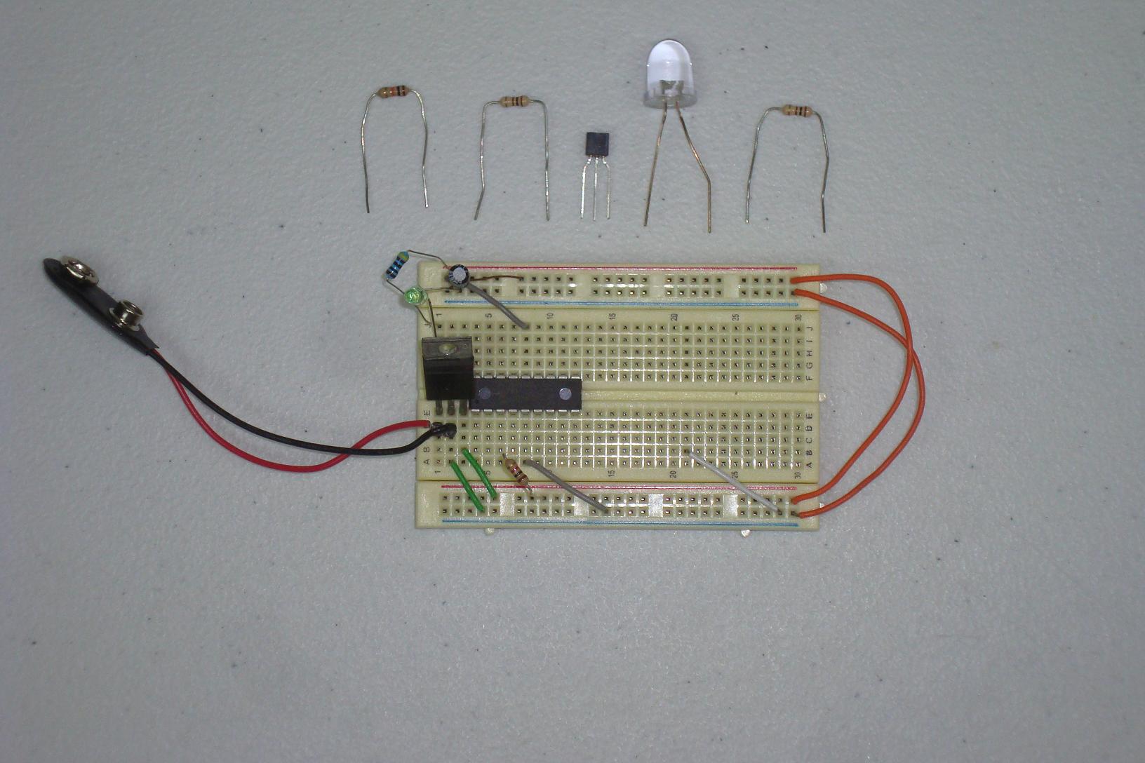
·Next the PIC circuit is wired up on the breadboard.

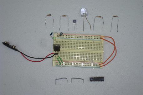
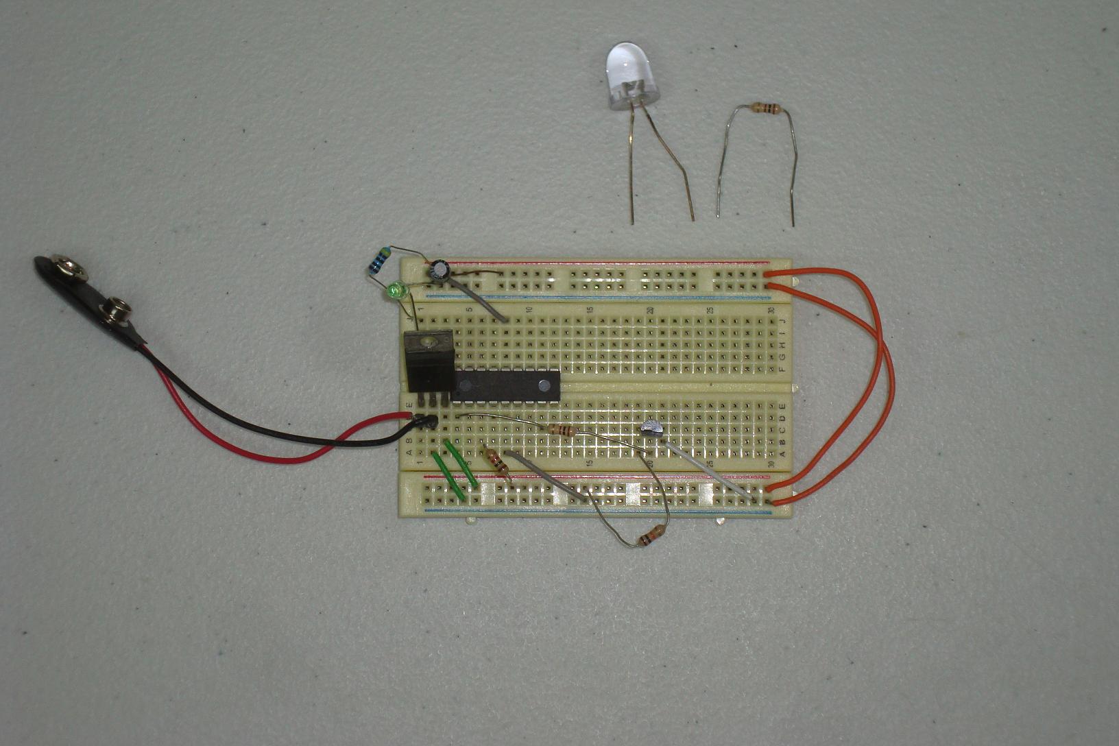
·The 2N2222 and resistors are connected to the PIC.
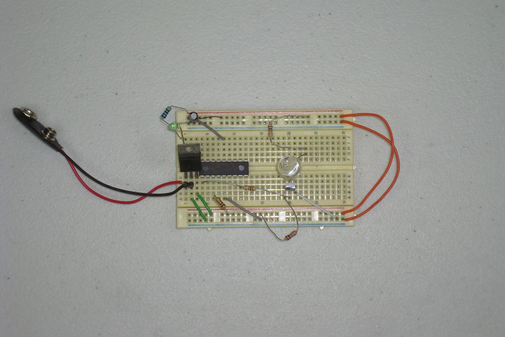
·Lastly, the LED and resistor is connected.

·Hopefully that was painless and quick, now it's time to move onto the firmware.
Now the fun part begins, we get to actually build the project. All the steps seen below follow the schematic and I added a power LED to know when the power is connected.
Building The Circuit
Get your parts together and follow the schematic. I assembled the circuit in stages as you can see below...
·First the power regulator circuit is connected.
·Next the PIC circuit is wired up on the breadboard.
·The 2N2222 and resistors are connected to the PIC.
·Lastly, the LED and resistor is connected.
·Hopefully that was painless and quick, now it's time to move onto the firmware.