Schematic Overview
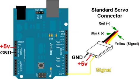
Since the Arduino comes as a pre-assembled platform, the hardware connections an schematic for this project is exceedingly simple. Only 3 wires! Can you believe it? The connections can be seen in the diagram below:
View Full Schematic
Schematic Specifics
+5v Servo Power From Arduino
Motors can suck a lot of current and the voltage regulators on the Arduino board are not meant to supply the kinds of current some motors can demand. This said, if you plan to connect many servos to an Arduino, make sure you have a seperate power supply that you connect directly to the servo motors. The Arduino UNO board can easily control and power 1 servo motor, but not 5,6,7 or 8...you'll burn something up on the board if you try. So I'm just making a simple and easy to wire-up example here.
Servo Signal Connection
Any of the digital pins on the right hand side of the board can be used to output the servo control signal. I chose digital pin 0 since it's numerically the first. Digital Pin 0 is also part of the serial Tx/Rx that Arduino uses to upload new programs so make sure to unplug your servo from this pin when uploading new programs, otherwise program uploads through Arduino will fail because the servo motor will think you're sending it signals that are really meant for the Arduino bootloader!
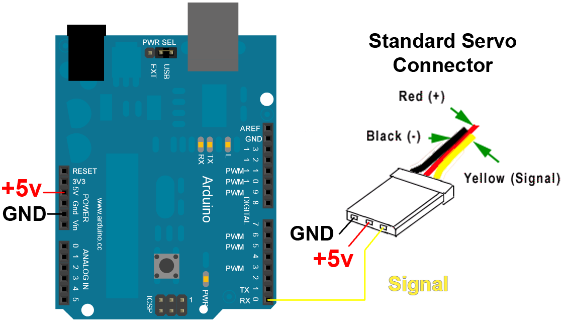